Table of Contents
Advertisement
Quick Links
RX-V1
Natural Sound AV Receiver
Ampli-Tuner Audio-Video
NATURAL SOUND AV RECEIVER RX-V1
CINEMA DSP
D I G I T A L
STANDBY/ON
SPEAKERS
A
B
PROGRAM
EFFECT
6CH IMPUT
A/B/C/D/E
PHONES
BASS
TREBLE
BALANCE
BASS
PROCESSOR
EXTENSION
DIRECT
0
0
1
1
1
1
1
1
2
2
2
2
2
2
3
3
3
0
3
3
3
4
4
4
4
4
4
–
+
–
+
5
5
5
5
L
5
5
R
ON
OFF
TRANSMIT RE-NAME
SYSTEM
POWER
D-TV
VCR 1
D I G I T A L
DOLBY
S U R R O U N D
VOLUME
SOURCE
INPUT SELECTOR
%
SELECT
%
POWER
/
10KEY DSP
INPUT MODE
EX/ES
CHP/INDEX
PRESET/TUNING
PRESET/TUNING
FM/AM
MEMORY
TUNING MODE
A / B / C / D / E
+
EDIT
MANL/AUTO FM
AUTO/MANL MONO
REC OUT/ZONE 2
TV INPUT
VIDEO AUX
SOURCE/REMOTE
TV VOL
LD
DVD
S VIDEO
VIDEO
L
AUDIO
R
D-TV
MD
TV MUTE
–
CBL/SAT
TAPE
VCR 1
TUNER
VCR 2
CD
VCR 3
PHONO
VIDEO AUX
OWNER'S MANUAL
MODE D'EMPLOI
UCA
MACRO
CLEAR
LEARN
MACRO
OFF
ON
STANDBY
V-AUX
TAPE
PHONO
CBL/SAT
TUNER
MD
CD
VCR 2
VCR 3
LD
DVD
6CH INPUT
%
TITLE
ENTER
%
DISPLAY
MENU
SOUND
SEARCH
–
CHAPTER
+
!
! $
$
REC
STOP
PAUSE
PLAY
*
#
HALL 1
HALL 2
CHURCH JAZZ CLUB
1
2
3
4
ROCK
ENTER-
CONCERT
CONCERT
CONCERT
TAINMENT
VIDEO 1
VIDEO 2
5
6
7
8
TV
MOVIE
MOVIE
/DTS
THEATER
THEATER 1
THEATER 2
SUR.
9
10
11
12
0
+10
+100
PRESET
+
+
MUTE
CH
VOLUME
EFFECT
–
–
DISC
Advertisement
Chapters
Table of Contents

Related Manuals for Yamaha RX-V1


Summary of Contents for Yamaha RX-V1
- Page 1 RX-V1 Natural Sound AV Receiver Ampli-Tuner Audio-Video D I G I T A L DOLBY NATURAL SOUND AV RECEIVER RX-V1 CINEMA DSP D I G I T A L S U R R O U N D INPUT SELECTOR STANDBY/ON...
-
Page 2: Safety Instructions
CAUTION RISK OF ELECTRIC SHOCK DO NOT OPEN CAUTION: TO REDUCE THE RISK OF ELECTRIC SHOCK, DO NOT REMOVE COVER (OR BACK). NO USER-SERVICEABLE PARTS INSIDE. REFER SERVICING TO QUALIFIED SERVICE PERSONNEL. • Explanation of Graphical Symbols The lightning flash with arrowhead symbol, within an equilateral triangle, is intended to alert you to the presence of uninsulated “dangerous voltage”... - Page 3 Yamaha Corporation of America or its subsidiaries. Since hearing damage from loud sounds is often undetectable until it is too late, YAMAHA and the Electronic Industries Association’s Consumer Electronics Group recommend you to avoid prolonged exposure from excessive volume levels.
- Page 4 Using this unit with a higher voltage than specified is dangerous and may result in fire or other accidents. YAMAHA will not be held responsible for any damage resulting from the use of this unit with a voltage other than that specified.
-
Page 5: Table Of Contents
Contents Introduction Features ... 3 Getting Started ... 5 Controls and Functions ... 6 Preparations Speaker System Configurations ... 13 Speaker Placement ... 14 Hookups ... 15 On-Screen Displays (OSD) ... 26 Speaker Settings ... 27 Speaker Output Levels ... 27 Basic Operation Basic Playback ... - Page 6 Introduction Features Introduction ... 3 Dolby Digital and Dolby Digital Surround EX ... 3 DTS and DTS ES ... 3 Comparing Surround Technologies ... 3 Digital Sound Fields (DSP) ... 4 Multi-function remote control ... 4 Various Input and Output Jacks ... 4 Built-in 8-channel power amplifier ...
-
Page 7: Features
DTS and DTS ES The RX-V1 is also equipped with a DTS decoder, which uses a 5.1 channel system to create a full surround sound environment. It was developed as a way to replace the analog soundtracks of movies with six channels of digital sound. In comparison with Dolby Digital, DTS uses less compression to store the sound information. -
Page 8: Digital Sound Fields (Dsp)
Various Input and Output Jacks The RX-V1 has various output jacks for audio and video signals as well as a digital recording output jack. Many input jacks are also available for connection to multiple audio-video sources. All the video inputs and outputs have S-video jacks in addition to standard composite video jacks for improved video picture quality. -
Page 9: Getting Started
In this case, change the direction of the light or reposition the main unit to avoid direct lighting. D I G I T A L CINEMA DSP DOLBY NATURAL SOUND AV RECEIVER RX-V1 D I G I T A L S U R R O U N D VOLUME... -
Page 10: Controls And Functions
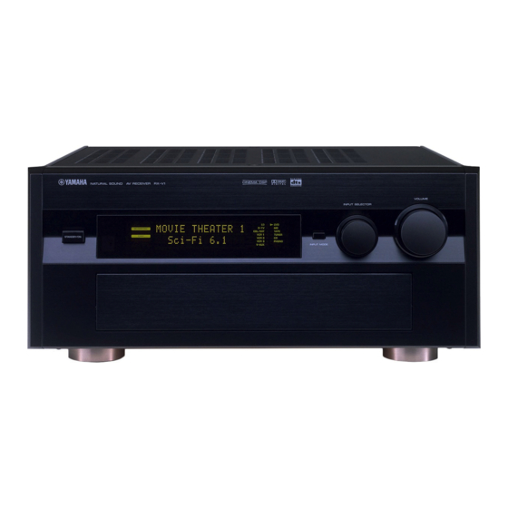
Front Panel NATURAL SOUND AV RECEIVER RX-V1 STANDBY/ON ~ STANDBY/ON Turns this unit on (On mode) and off (Standby mode). When you turn on this unit, you will hear a click and there will be a four to five to second delay before this unit can reproduce sound. -
Page 11: Opening And Closing The Front Panel Door
fi EFFECT Switches the effect speakers (Center, Front Effect, Rear and Rear Center) on and off. If you turn off the output of these speakers using EFFECT, all DTS and Dolby Digital audio signals are directed to the Main left and right channels except for the LFE channel. -
Page 12: Remote Control
Remote Control Power Buttons Turn the power on and off. Press SYSTEM POWER to turn on the power and STANDBY to turn off (Standby mode) the power to the main unit. Display Window Shows the source component that you select to control. Source Select Selects the source component without switching the input. -
Page 13: Sleep Timer
~ Infrared window Outputs infrared control signals. Aim this window at the component you want to operate. Ÿ CLEAR Used for clearing functions acquired using the Learn and Rename features, programmed macros, and preset manufacturer codes (see pages 65, 66). ! RE-NAME Used for changing the source name in the display window (see page 65). -
Page 14: Front Panel Display
Front Panel Display VIRTUAL DIGITAL PRO LOGIC SPEAKERS ~ DTS indicator Lights up when the built-in DTS decoder is on. Ÿ VIRTUAL indicator Lights up when using Virtual Cinema DSP (See page 34.) ! Multi-information display Shows the current DSP program and other information when adjusting or changing settings. -
Page 15: Rear Panel
Rear Panel RF (AC-3) input jack Connect to the RF output terminal of your LD player. Ÿ Audio equipment jacks Refer to page 16 for hookup information. ! Video equipment jacks Refer to page 18 for hookup information. ⁄ Antenna input terminals Refer to page 25 for hookup information. - Page 16 Preparations Speaker System Configurations Eight or Seven Speaker Configuration –Full Cinema DSP– ... 13 Six Speaker Configuration –Hi Fi DSP– ... 13 Five Speaker Configuration –Standard 5.1 Channel– ... 13 Four Speaker Configuration –Minimum Requirement– ... 13 Speaker Placement Placing the Main Speakers ... 14 Placing the Center Speaker ...
-
Page 17: Speaker System Configurations
The most complete speaker configuration consists of eight speakers: the left and right Main speakers, a Center speaker, the left and right Rear speakers, the left and right Front Effect speakers, and a Rear Center speaker. If you do not use eight speakers, you can direct the signals for speakers that are not in your system to other speakers in your configuration. -
Page 18: Speaker Placement
Where you place your speakers has a tremendous effect on how well your system sounds. TV or Video Main monitor speaker TV or Video monitor Center speaker approx. 0.5~1m 1.5~3m 0.5~1m (3ft) (1~3ft) (5~15ft) (1~3ft) Placing the Subwoofers Place the Front Subwoofer near the Main speakers. Turn it slightly toward the center of the room to reduce wall reflections. If you use a Rear Subwoofer, place it behind the main listening position. -
Page 19: Hookups
Connecting to Digital Jacks The RX-V1 has digital jacks for direct transmission of digital signals through either coaxial or fiber optic cables. You can use the digital jacks to input PCM, DTS and Dolby Digital bitstreams. When you connect components to both the COAXIAL and OPTICAL jacks (for CD, DVD, and CBL/SAT) priority is given to the input signals from the COAXIAL jack. -
Page 20: Connecting Audio Components
When you connect other YAMAHA audio equipment (such as a CD player or changer, MD deck, or tape deck, connect to terminals with the same number labels. Yamaha applies this labelling system to all its products. -
Page 21: Connecting A Tape Deck
• You can monitor audio recordings if you connect a three-head tape deck to the TAPE 3 (PLAY) jacks. • When you connect a tape deck to the RX-V1, keep the deck’s power on while using the RX-V1. If the power is off, the RX-V1 may distort the sound from other equipment. -
Page 22: Connecting Video Components
Connecting Video Components Before you connect any components, disconnect the power supply to all the components you plan to connect including the RX-V1 and determine which jacks are for the left and right channels and for input and output. After you finish all hookups, check them again to make sure they are correct. -
Page 23: Connecting A Vcr
VIDEO jack. Notes: • You can connect other VCRs to the RX-V1 using the VCR 2 and VCR 3 jacks. • If your VCR has an optical digital signal output jack, connect it to the OPTICAL VCR 1 jack of this unit. -
Page 24: Connecting Speakers
Connecting Speakers This section explains how to connect speakers to the RX-V1. After you finish connecting your speakers, use the SET MENU to change the signal output settings according to the number and size of the speakers in your configuration. - Page 25 Right Front Left Front Effect Speaker Effect Speaker SPEAKERS FRONT – – REAR – – – – CENTER REAR CENTER SPEAKERS FRONT – – REAR – – – – CENTER REAR CENTER Right Rear Left Rear Speaker Speaker Rear Center Speaker Subwoofer system PREOUT/MAIN IN FRONT...
-
Page 26: Impedance Selector Switch
Be sure to connect the Rear speakers to the Subwoofer with the correct polarity. Note: • Adjust the speaker volume for the Subwoofer with the controls on the Subwoofers, not on the RX-V1. Impedance Selector switch Select the position whose requirements your speaker system meets. (Upper position) Front Effect: The impedance of each speaker must be 6 or higher. -
Page 27: Connecting External Amplifiers
The signals output through these jacks are affected by BASS, TREBLE, BALANCE, and BASS EXTENSION settings. MAIN IN jacks ... Line input to the RX-V1 Main channel amplifiers. Ÿ CENTER jacks CENTER OUT jack . Center channel line output jacks. -
Page 28: Connecting An External Decoder
Connecting an External Decoder The RX-V1 is equipped with six additional input jacks (left and right MAIN, CENTER, left and right SURROUND and SUBWOOFER) for discrete multi-channel input from an external decoder, sound processor, or pre-amplifier. MAIN SURROUND D-TV WOOFER... -
Page 29: Connecting The Antennas
Connecting the Antennas Both AM and FM indoor antennas are included with this unit. These antennas should provide sufficient signal strength in most situations. However, a properly installed outdoor antenna provides clearer reception. If you experience poor reception quality using the indoor antennas, an outdoor antenna may improve the reception. -
Page 30: On-Screen Displays (Osd)
You can display the operation information for this unit on a video monitor. If you display the SET MENU and DSP sound field program parameter settings on a screen, it is much easier to see the available options and parameters than it is by reading this information on the front panel display. -
Page 31: Speaker Settings
The RX-V1 has seven SPEAKER SET items in the SET MENU that you must set according to the number of speakers in your configuration and their size. The following table summarizes these SPEAKER SET items, and shows the initial settings as well as other possible settings. If the initial settings are not appropriate for your speaker configuration, change the settings in the SET MENU (see page 41). -
Page 32: Dolby Surround Test
Dolby Surround Test Use the Dolby Surround Test to balance the output levels of speakers required for surround sound systems. TEST Speaker Output Levels Press TEST on the remote control so “TEST DOLBY SUR.” appears on the video monitor and front panel display. Adjust VOLUME +/–... -
Page 33: Dsp Test
DSP Test Adjust the output level of the Front Effect speakers while this unit is reproducing a DSP sound field program. If you do not use Front Effect speakers, set the 1F. FRNT EFCT SP item in the SET MENU to “NONE” (see page 41), and the DSP Front Effect signals will be mixed with the Main channel signals. -
Page 34: Basic Operation
Basic Operation Basic Playback Power Control ... 31 Selecting a Source ... 32 Input Modes and Indications ... 33 Selecting a Sound Field Program ... 34 AM/FM Tuner Manual Tuning ... 35 Automatic Tuning ... 35 Presetting Stations ... 36 Tuning to Preset Stations ... -
Page 35: Basic Playback
– DISC Power Control SYSTEM POWER STANDBY STANDBY/ON SYSTEM POWER STANDBY STANDBY/ON Basic Playback STANDBY/ON STANDBY/ON NATURAL SOUND AV RECEIVER RX-V1 STANDBY/ON SPEAKERS PROGRAM EFFECT 6CH IMPUT PHONES BASS TREBLE BALANCE – – VOLUME EFFECT Press STANDBY/ON (or SYSTEM POWER on the remote control) to turn on the power. -
Page 36: Selecting A Source
Selecting a Source V-AUX INPUT SELECTOR D-TV CBL/SAT TUNER VCR 1 VCR 2 VCR 3 The selected source D-TV CBL/SAT TAPE VCR 1 TUNER VCR 2 VCR 3 PHONO V-AUX VOLUME VOLUME – Basic Playback Select the source using INPUT SELECTOR, or press one of the TAPE PHONO input buttons on the remote control. -
Page 37: Input Modes And Indications
Input Modes and Indications The RX-V1 comes with various input jacks. If your external component is connected to more than one type of input jack, you can set the priority of the input signal. Press INPUT MODE on the front panel or an input button (press it repeatedly) on the remote control to display or change the input mode. -
Page 38: Selecting A Sound Field Program
Selecting a Sound Field Program You can enhance your listening experience by selecting a DSP sound field program. The 24 DSP sound field programs are divided into 12 DSP program groups. For details about each program, see pages 71~76. 10KEY/DSP 6.1/ES If you want to utilize the Rear Center speaker with a 5.1 channel program... -
Page 39: Am/Fm Tuner
Automatic tuning is effective when the radio signals are strong and have no interference. However, manual tuning is best for weaker signals that have some interference. Manual Tuning FM/AM TUNING MODE AUTO/MAN’L MONO PRESET/TUNING Automatic Tuning FM/AM TUNING MODE AUTO AUTO/MAN’L MONO PRESET/TUNING AM/FM Tuner... -
Page 40: Presetting Stations
Presetting Stations MEMORY MEMORY MAN’L/AUTO FM A/B/C/D/E SPEAKERS PRESET/TUNING MEMORY MAN’L/AUTO FM SPEAKERS Shows the displayed station has been programmed to A-1. AM/FM Tuner Manually presetting stations This unit can store up to 40 stations (8 stations x 5 groups). Using this feature, you can easily tune to any preset station by selecting the preset station number (see page 38). - Page 41 MEMORY MAN’L/AUTO FM SPEAKERS AM/FM Tuner Automatically presetting stations You can use the automatic preset tuning feature to store FM stations. With this function, the unit automatically tunes to FM stations with strong signals, then stores up to 40 of those stations in order. Tune to the FM station from which you want automatic presetting to begin.
-
Page 42: Tuning To Preset Stations
Tuning to Preset Stations A/B/C/D/E SPEAKERS PRESET/TUNING EDIT SPEAKERS PRESET/TUNING SPEAKERS Exchanging Preset Stations You can exchange the stations stored on two preset numbers. The example below describes the procedure for exchanging the stored stations at preset numbers E1 and A5. PRESET/TUNING EDIT SPEAKERS... -
Page 43: Basic Recording
PHONO VIDEO AUX Basic Recording Turn on the power to the RX-V1 and all connected equipment. Select the source equipment you want to record using REC OUT/ ZONE 2. • To record the current source, set REC OUT/ZONE 2 to SOURCE/ REMOTE. -
Page 44: Advanced Operation
Advanced Operation SET MENU Items Operating the SET MENU ... 42 1. SPEAKER SET (1A. CENTER SP to 1G. MAIN LEVEL) ... 43 2. LOW FREQ. TEST ... 46 3. DOLBY D. SET (Dolby Digital Set) ... 47 4. DTS SET ... 48 5. -
Page 45: Set Menu Items
The SET MENU consists of eighteen items including the Speaker Set, Center Graphic Equalizer and Parameter Initialization features. Choose the appropriate item and adjust or select the values as necessary. Notes: • You can adjust the items in the SET MENU while reproducing a source. •... -
Page 46: Operating The Set Menu
Operating the SET MENU This section describes how to adjust items in the SET MENU using the remote control. General procedure for adjusting items Some items require extra steps to change to the desired setting. Set PARAMETER/SET MENU to SET MENU. PARAMETER SET MENU repeatedly to select an item, then press + or –... -
Page 47: Speaker Set (1A. Center Sp To 1G. Main Level)
1A. CENTER SP (Center Speaker Mode) By adding a Center speaker to your speaker configuration, the RX-V1 can provide good dialogue localization for many listeners and superior synchronization of sound and images. The OSD shows a large, small or no center speaker depending on how you set this item. - Page 48 1D. REAR CT SP (Rear Center Speaker Mode) By adding a Rear Center speaker to your speaker configuration, the RX-V1 can provide more realistic front-to-back and back-to-front transitions. The initial setting is “LRG”. Select the “LRG” setting if you have a large Rear Center speaker. The entire range of Rear Center channel signals is sent to the Rear Center speakers.
- Page 49 1F. FRNT EFCT SP (Front Effect Speaker Mode) The RX-V1 uses Front Effect speakers to localize the virtual sound sources of the sound field programs. If you do not use Front Effect speakers, you can direct the Front Effect signals to the Main speakers.
-
Page 50: Low Freq. Test
2. LOW FREQ. TEST Use this feature to adjust the Subwoofer volume so it matches the volume of the other speakers in your configuration. Change the setting using the remote control while sitting in the main listening position. Press + or – to set the TEST TONE to “ON”, and adjust the volume using VOLUME + so you can hear the tone. Press repeatedly to go to OUTPUT and press + or –... -
Page 51: Dolby D. Set (Dolby Digital Set)
3. DOLBY D. SET (Dolby Digital Set) 3A. LFE LEVEL Use this feature to adjust the output level of the LFE (low frequency effect) channel when playing back Dolby Digital encoded software. This setting is effective only when this unit decodes Dolby Digital signals. The LFE signal carries the low frequency special effect sound which is only added to certain scenes. -
Page 52: Dts Set
4. DTS SET 4A. LFE LEVEL Use this feature to adjust the output level of the LFE (low frequency effect) channel when playing back DTS encoded software. This setting is effective only when this unit decodes DTS signals. The LFE signal carries the low frequency special effect sound which is only added to certain scenes. -
Page 53: Center Geq (Center Graphic Equalizer)
7. CENTER GEQ (Center Graphic Equalizer) Use this feature to adjust the built-in five band graphic equalizer so the Center speaker tone matches that of the left and right Main speakers. You can select the 100 Hz, 300 Hz, 1 kHz, 3 kHz, or 10 kHz frequencies. to select a higher frequency and % to select a lower frequency. -
Page 54: Cinema Eq
9. CINEMA EQ Use this feature to match the tonal quality of four groups of speakers: the Main and Center speaker group, the Front Effect speakers group, the Rear speakers group, and the Rear Center speaker group. CINEMA-EQ consists of a high-shelving equalizer (HIGH) and a parametric equalizer (PEQ). -
Page 55: Hp Tone Ctrl (Headphone Tone Control)
10. HP TONE CTRL (Headphone Tone Control) Use this feature to adjust the level of bass and treble when you use your headphones. The initial Setting is 0 dB for both bass and treble. This does not effect to the 96 kHz sampling digital signal. Select BASS or TRBL and press + or –... -
Page 56: 13. Memory Guard
13. MEMORY GUARD Use this feature to prevent accidental changes to DSP program parameter values and other settings on this unit. Select “ON” to use MEMORY GUARD to protect the following features: • DSP program parameters • All SET MENU items •... -
Page 57: 16. Input Rename
16. INPUT RENAME Use this feature to change the name of the input which appears on the OSD or the front panel display. Select the input you want to change the name of by pressing an input button (or using INPUT SELECTOR). Press + or –... -
Page 58: Remote Control Features
The remote control can operate the main unit as well as other Yamaha audio and video components. To control the components of other manufacturers (or some Yamaha), you must set up the remote control with the manufacturer’s codes. This remote control also has a sophisticated Learn feature that allows it to acquire functions from the remote controls of other components in your system (or other household appliances) equipped with infrared remote control receivers. -
Page 59: Source Select
SOURCE SELECT You can control another component independently from the input you selected by pressing an input button. Press SELECT to choose a component and set the remote control to be used for it. The display window will show one of the following: V-AUX, TAPE, PHONO, D-TV (digital and regular TV), CBSAT (Cable TV/Satellite TV), TUNER, MD, CD, VCR 1, VCR 2, VCR 3, LD, DVD, Zone2, OPTN (Option). -
Page 60: Each Component Control Area
Each Component Control Area The general operational buttons are shown for each area. Some of them may not function depending on the equipment you have. Operating a Tuner (TUNER Area) POWER Preset group A Preset group B Operating a Tape Deck (TAPE Area) Fast forward Rewind REC / PAUSE... -
Page 61: Operating A Cd Player (Cd Area)
TV VOL VOLUME TV MUTE EFFECT – – – DISC Skip Search PLAY PAUSE (YAMAHA : Pause / Stop) Numeric buttons 1 to 9 CLEAR Numeric button +10 Numeric button 0 DISC +/– (Disc Skip) Skip Search PLAY PAUSE STOP... -
Page 62: Operating An Ld Player (Ld Area)
Operating an LD Player (LD Area) DISPLAY SEARCH POWER STOP Chapter / Time TV VOL +/–, TV INPUT, and TV MUTE function if you have set up the manufacturer code for the D-TV Area. Operating a DVD Player (DVD Area) TITLE MENU DISPLAY... -
Page 63: Operating A Vcr (Vcr1/Vcr2/Vcr3 Area)
Operating a VCR (VCR 1 / VCR 2 / VCR 3 Area) Rewind / Fast Forward POWER (Press twice) TV / VIDEO TV VOL +/–, TV INPUT, and TV MUTE function if you have set up the manufacturer code for the D-TV Area. Operating a TV or Digital TV (D-TV Area) DISPLAY POWER... -
Page 64: Operating A Cable Or Satellite Tv Tuner (Cbsat Area)
Operating a Cable or Satellite TV Tuner (CBSAT Area) DISPLAY MENU POWER Enter TV VOL +/–, TV INPUT, and TV MUTE function if you have set up the manufacturer code for the D-TV Area. Free Area (OPTN and PHONO Areas) SELECT POWER 10KEY DSP... -
Page 65: Seting The Manufacturer Code In The Remote Control
You can control other components by setting a manufacturer code. A code can be set up in each component controol area except for the OPTN area. The Yamaha code is factory preset for DVD, LD, CD, MD, TUNER, and TAPE (Yamaha for LD, and Yamaha1 for others). -
Page 66: Programming A New Remote Control Function
Programming a New Remote Control Function If you desire to program functions not included in the basic operations covered by the manufacturer code, or a manufacturer code is not available, the following procedure needs to be performed. The possible programming area is the same as a component control area, so buttons are programmable independently for each source component area. -
Page 67: Using The Macro Feature
STANDBY *1 In order to turn on some Yamaha components connected to this unit, connect those components to AC OUTLETS on the rear panel. *2 If the macro you select includes power on/off functions, the equipment may turn off if it is already on when you press the macro button. For example, if your TV is on and you press the SYSTEM POWER macro button, the TV turns off. - Page 68 Operating the Macro Feature MACRO ON/OFF MACRO TRANSMIT RE-NAME CLEAR LEARN MACRO SYSTEM POWER STANDBY V-AUX TAPE PHONO D-TV CBL/SAT TUNER VCR 1 VCR 2 VCR 3 6CH INPUT TITLE ENTER Programming a Macro You can use the Macro feature to transmit many remote control commands by pressing a single button. MACRO SYSTEM POWER...
-
Page 69: Changing The Source Name In The Display Window
Changing the Source Name in the Display Window SYSTEM POWER STANDBY V-AUX TAPE PHONO D-TV CBL/SAT TUNER VCR 1 VCR 2 VCR 3 RE-NAME 6CH INPUT TITLE ENTER SOURCE DISPLAY MENU SOUND SELECT SEARCH – CHAPTER POWER STOP PAUSE PLAY RE-NAME Clearing a Learned Function or Macro SYSTEM... -
Page 70: Clearing Learned Functions, Macros, Renamed Displays, And Manufacturer Setups
Clearing Learned Functions, Macros, Renamed Displays, and Manufacturer Setups CLEAR 6CH INPUT TITLE ENTER SOURCE DISPLAY MENU SOUND SELECT SEARCH – CHAPTER POWER STOP PAUSE PLAY For example, when DVD is selected as the source component. CLEAR CLEAR Notes: • If the remote control is without batteries for more than twenty minutes, or if worn out batteries remain in the unit, the contents of the memory may be cleared. -
Page 71: Adjusting The Levels Of The Effect Speakers
Adjusting the Levels of the Effect Speakers You can adjust the volume level of each effect speaker (Center, Right Rear, Rear Center, Left Rear, Front Effect, and Subwoofer) while listening to a music source. Center PARAMETER ON SCREEN LEVEL SET MENU SLEEP TEST Right Rear... -
Page 72: Zone 2
Remote 1 • Some Yamaha models are able to connect directly to the REMOTE 1 OUT jacks of this unit. If you own these products, you may not need to use an infrared emitter. Up to six Yamaha components can be connected as shown. -
Page 73: Remote Control In Zone 2
Remote Control in ZONE 2 In the second (Zone 2) room, the supplied remote control can be used as the Zone 2 remote control. You can select the input source and control the component which is located in the main room directly from the second room regardless of the listening condition in the main room. - Page 74 Additional Information Digital Sound Field Processing (DSP) Understanding Sound Fields ... 71 Recreating a Sound Field ... 71 E/R (Early Reflection) ... 71 4ch REV. (Four Channel Reverberation) ... 71 Illustration of the Virtual Sound Sources and Echo Patterns ... 71 Hi-Fi DSP-Sound Field Program Program Group 1 : Concert Hall 1 ...
-
Page 75: Digital Sound Field Processing (Dsp)
This type of program consists of early reflections and high quality digital reverberation processing. Reverberation is the most important element for recreating the sound field of a church. To recreate a realistic spatial sound image from reverberation data, Yamaha has adapted the four-channel-output reverberation technology. -
Page 76: Hi-Fi Dsp-Sound Field Program
Program Group 1 : Concert Hall 1 Europe Hall A This is a large fan-shaped concert hall in Munich which has approximately 2500 seats. Almost the whole interior is made of wood. There is relatively little reflection from the walls, and sound spreads finely and beautifully. -
Page 77: Cinema-Dsp
CINEMA-DSP is an upgraded version of YAMAHA DSP specially designed for movie soundtracks. CINEMA-DSP integrates the DTS, Dolby Digital, and Dolby Pro Logic surround sound technologies with YAMAHA DSP sound field programs to provide the surround sound field. It recreates the most complete movie sound design in your audio room. In CINEMA-DSP sound field programs, Yamaha’s exclusive DSP processing is added to the front left, center, and right channels, so the listener can enjoy realistic dialogue, depth of sound, smooth transition between sound sources, and a surround sound field that goes beyond the screen. -
Page 78: Movie Theater Programs
The built-in Dolby Digital decoder brings the professional quality sound designed for movie theaters, into your home. With the RX-V1’s Movie Theater program, you can recreate a dynamic sound that gives you the feeling of being at a public theater in your living room using the Dolby Digital technology. -
Page 79: Cinema-Dsp Sound Field Program
CINEMA-DSP Sound Field Program According to the input signal format, the RX-V1 automatically chooses the appropriate decoder and DSP sound field pattern. Table of Program Names for Each Input Format Input Stereo Program (2ch) Group Pop/Rock CONCERT VIDEO 1 Classical/Opera... -
Page 80: Program Group 7 : Concert Video 1
Program Group 7 : Concert Video 1 Pop/Rock This program produces an enthusiastic atmosphere and lets you feel as if you are at an actual jazz or rock concert. Program Group 8 : Concert Video 2 Classical/Opera This program provides excellent vocal depth and overall clarity by restraining excessive reverberation. -
Page 81: Sound Field Program Parameter Editing
Sound Field Program Parameter Editing You can enjoy good quality sound with the pre-set parameters. Although you do not have to change the initial settings, you can change some of the parameters to better suit the input source or your listening room. Changing Parameter Settings PARAMETER SET MENU... -
Page 82: Digital Sound Field Parameter Descriptions
Digital Sound Field Parameter Descriptions You can adjust the values of certain digital sound field parameters so the sound fields are recreated accurately in your listening room. Not all of the following parameters are found in every program. EFCT TRIM (Effect Trim) Function ... -
Page 83: Dly (Surround Delay)
Digital Sound Field Parameter Descriptions S. DLY (Surround Delay) Function ... This parameter adjusts the delay between the direct sound and the first reflection in the surround sound field. Control Range ... 0 - 49 milliseconds (The range depends on the signal format.) Description ... -
Page 84: Rc. Room Size (Rear Center Room Size)
Digital Sound Field Parameter Descriptions RC. ROOM SIZE (Rear Center Room Size) Function ... This parameter adjusts the apparent size of the rear center sound field. Control Range ... 0.1 - 2.0 Description ... The larger the value, the more reflective the presence sound field walls become. S. -
Page 85: Rev. Time (Reverberation Time)
Digital Sound Field Parameter Descriptions REV. TIME (Reverberation Time) Function ... This parameter adjusts the amount of time it takes for the dense, subsequent reverberation sound to decay by 60 dB (at 1 kHz). This changes the apparent size of the acoustic environment over an extremely wide range. Control Range ... -
Page 86: Appendix
Appendix Troubleshooting Reference Chart for the INPUT and OUTPUT Jacks CINEMA - EQ Frequency Characteristics Specifications... -
Page 87: Troubleshooting
Refer to the chart below when the RX-V1 does not function properly. If the problem you are experiencing is not listed below or if the instruction below does not help, turn the power off, disconnect the power cord, and contact your dealer or the nearest Yamaha Audio Products Service Department. - Page 88 Problem No sound is coming from the Effect speakers. No sound is coming from the Front Effect speakers. No sound is coming from the Center speaker. No sound is coming from the Rear Effect speakers. No sound is coming from the Subwoofer.
- Page 89 Problem Possible Cause A source cannot be recorded The source unit is connected to this unit by a tape deck or VCR using digital jacks only. connected to this unit. CHECK SP WIRES!" appears Speaker cables are short circuited. on the display. There is noise from a nearby This unit is too close to the affected TV or tuner.
- Page 90 Remote Control Problem The remote control does not work. The remote control does not function properly. The remote control does not “learn” new functions. (The TRANSMIT indicator does not light up or flash.) Continuous functions such as volume are learned, but operate only for a moment before stopping.
-
Page 91: Reference Chart For The Input And Output Jacks
Reference Chart for the INPUT and OUTPUT Jacks SIGNAL ANALOG PHONO TUNER TAPE D-TV CBL/SAT VCR 1, 2, 3 V-AUX 6 CH INPUT SUBWOOFER ZONE 2 OUT MONITOR OUT SPEAKER OUT HEADPHONES *1 This input can be changed to another video input by using the SET MENU. *3 SPLIT L,R, and MONO outputs *4 MAIN L,R, CENTER, FRONT L,R, REAR L,R, and REAR CENTER total 8 channels CINEMA - EQ Frequency Characteristics... -
Page 92: Specifications
Audio Section Minimum RMS Output Power per Channel MAIN L/R, CENTER, REAR L/R/C (20 Hz to 20 kHz, 0.015% THD, 8 ohms) ------------ 110 W FRONT L/R (1 kHz, 0.05% THD, 8 ohms) ------------ 35 W Dynamic Power (IHF) MAIN L/R (8/6/4/2 ohms) -------------- 150/180/240/340 W Dynamic Headroom MAIN L/R (8 ohms) -------------------------------------- 1.3 dB Power Band Width... - Page 93 YAMAHA ELECTRONIQUE FRANCE S.A. RUE AMBROISE CROIZAT BP70 CROISSY-BEAUBOURG 77312 MARNE-LA-VALLEE CEDEX02, FRANCE YAMAHA ELECTRONICS (UK) LTD. YAMAHA HOUSE, 200 RICKMANSWORTH ROAD WATFORD, HERTS WD1 7JS, ENGLAND YAMAHA SCANDINAVIA A.B. J A WETTERGRENS GATA 1, BOX 30053, 400 43 VÄSTRA FRÖLUNDA, SWEDEN Printed in Japan V482920-1 YAMAHA MUSIC AUSTRALIA PTY, LTD.
-
Page 94: Quick Reference Card
MENU SOUND SELECT SEARCH – CHAPTER SEARCH SKIP SEARCH POWER STOP PAUSE PLAY POWER PLAY PAUSE (YAMAHA : STOP PAUSE / STOP) 10KEY DSP HALL 1 HALL 2 CHURCH JAZZ CLUB ROCK ENTER- CONCERT CONCERT CONCERT TAINMENT VIDEO 1 VIDEO 2... - Page 95 Quick Reference Card SYSTEM POWER STANDBY V-AUX TAPE PHONO D-TV CBL/SAT TUNER VCR 1 VCR 2 VCR 3 6CH INPUT TITLE ENTER SOURCE DISPLAY SOUND DISPLAY MENU SOUND – SELECT SEARCH CHAPTER CHAPTER SEARCH SEARCH POWER STOP PAUSE PLAY POWER PLAY PAUSE STOP...
Need help?
Do you have a question about the RX-V1 and is the answer not in the manual?
Questions and answers