Table of Contents
Advertisement
Quick Links
Advertisement
Table of Contents
Troubleshooting

Related Manuals for Motorola C116


Summary of Contents for Motorola C116
- Page 1 Level 1-2 Service Manual C115 / C116 Dual Band Wireless Telephone GSM 900/1800...
-
Page 2: Table Of Contents
Table of Contents C115 Table of Contents Introduction ........................... 3 Product Identification ......................3 Product Names ........................3 Product Changes ........................3 Regulatory Agency Compliance ................... 3 Computer Program Copyrights ..................... 4 About This Service Manual ....................4 Warranty Service Policy ....................... 5 Parts Replacement ....................... -
Page 3: Introduction
Available on a contract basis, Motorola Inc. offers comprehensive maintenance and installation programs that enable customers to meet requirements for reliable, continuous communications. To learn more about the wide range of Motorola service programs, contact your local Motorola products representative or the nearest Customer Service Manager. -
Page 4: Computer Program Copyrights
Motorola computer programs in any manner or form without Motorola's prior written consent. Furthermore, the purchase of Motorola products shall not be deemed to grant either directly or by implication, estoppel, or otherwise, any license or rights under the copyrights, patents, or patent applications of Motorola, except for a nonexclusive license to use the Motorola product and the Motorola computer programs with the Motorola product. -
Page 5: Warranty Service Policy
Product Support The customer's original phones will be repaired but not refurbished as standard. Appointed Motorola Service Hubs will perform warranty and non-warranty field service for level 2 (assemblies) and level 3 (limited Transceiver component). Motorola High Tech Centers will perform level 4 (full component) repairs. -
Page 6: Parts Replacement
When ordering replacement parts or equipment, include the Motorola part number and description used in the service manual. When the Motorola part number of a component is not known, use the product model number or other related major assembly along with a description of the related major assembly and of the component in question. -
Page 7: Specifications
Level 1-2 Service Manual Specifications Specifications General Function Specification Dimensions 101mm X 47.8mm X 21.9mm Weight Not exceed 80 grams External LCD B&W, Active Area: 28.58 X 19.35mm, Pixel: 96 X 35 Band GSM900/1800 or GSM850/PCS1900 Battery 920mAh Li Ion Battery Product type Bar type Antenna... - Page 8 Specifications C115 Transmitter Function Specification RF Power Output 32 dBm nominal GSM900 29 dBm nominal DCS1800 Output Impedance 50 ohms nominal Spurious Emissions -36 dBm from 0.1 to 1GHz, -30 dBm from 1 to 4 GHz Receiver Function Specification Receive Sensitivity -107 dBm GSM 850/GSM900 -106 dBm DCS1800/PCS1900 Rx Bit Error Rate (100k bits) Type II...
-
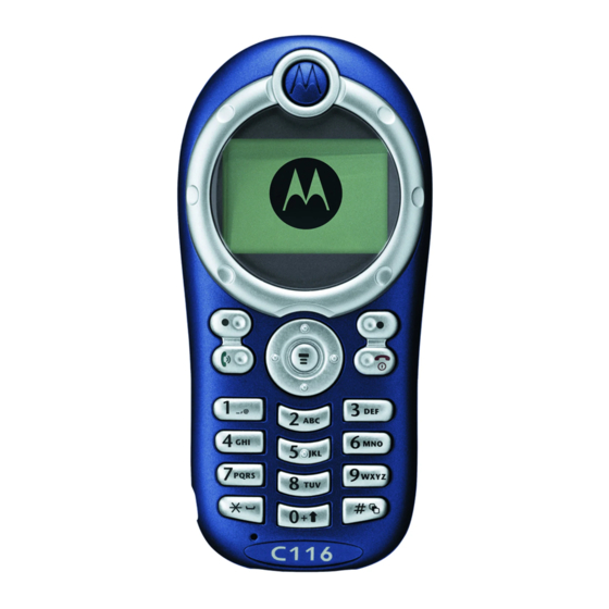
Page 9: Product Overview
Product Overview Product Overview The Motorola C155 features a global system for mobile communications wireless interface and general packet radio service (GPRS) transport technology. It also features a simplified icon and graphical user interface (UI) for easier operation in addition to short message service text messaging (SMS), speed dialing, quick dialing, an alarm, a calculator, games, and an address book. - Page 10 Product Overview C115 • Personal management tools calculator with currency converter, real time clock with date, reminders, and caller profiling • Other features Caller Line Identification Upon receipt of a call, the calling party's phone number is compared to the phone book. If the number matches a phone book entry, that name will be displayed.
-
Page 11: General Functions
Level 1-2 Service Manual General Functions General Functions Controls, Indicators, and Input/Output (I/O) Connectors The C115 phone's controls are located on the front side of the device and on the keyboard as shown in below. Indicators icons are displayed on the LCD. Antenna Enclosed on the top- Menu Key... - Page 12 General Functions C115 Liquid Crystal Display (LCD) The LCD provides a 700 square millimeter multicolor backlit color display with user- adjustable contrast settings for optimum readability in all light conditions. The bit-map 96 x 64 pixel display includes up to 3 lines of text, 1 line of icons, and 1 line of prompts. Icon Name Description...
-
Page 13: User Interface Menu Structure
Level 1-2 Service Manual General Functions User Interface Menu Structure The table below shows a portion of the C115 telephone menu structure. Menu Map • Call Forward * • Other Settings* • Voice Call • Personalize • Cancel All • Main Menu •... -
Page 14: Battery Function
Used to measure battery voltage 1. To order in North America, contact Motorola Aftermarket and Accessories Division (AAD) by phone at (800) 422-4210 or FAX (800) 622-6210. Internationally, AAD can be reached by calling (847) 538-8023 or by fax (847) 576-3023. -
Page 15: Disassembly
Level 1-2 Service Manual Disassembly Disassembly This section describes how to disassemble a C115 telephone. Tools and equipment used are listed on the preceding page. Many of the integrated devices used in this phone are vulnerable to damage from electrostatic discharge (ESD). -
Page 16: Removing And Replacing The Sim Card
Disassembly C115 To replace, insert the battery with 2 tabs on its bottom end into the battery slots of the phone as shown in Figure 5. Figure 5. Replacing the Battery Click the battery into place, then slip the battery cover over it. Removing and Replacing the SIM Card Remove the battery, as described earlier. -
Page 17: Removing And Replacing The Front Housing
Level 1-2 Service Manual Disassembly Removing and Replacing the Front Housing Remove the battery and SIM as described earlier. Grip the phone firmly with one hand. Figure 7. Grip the phone firmly with one hand Use a flat wedge tool to pry the case open along the central seam. Figure 8. -
Page 18: Removing And Replacing The Back Housing
Disassembly C115 Remove the front housing. Figure 9. Remove the front housing (Optional) Remove and replace the rubber keypad. It slips out of the front housing. To replace, simply snap the two halves together again. Replace the SIM card and battery. Removing and Replacing the Back Housing Remove the front housing as described earlier. - Page 19 Level 1-2 Service Manual Disassembly Using a size T5 screwdriver, remove 4 screws from the Transceiver board mounted in the back housing. Figure 11. Remove 4 screws June 1, 2004...
- Page 20 Disassembly C115 Pry open the side latches securing the Transceiver board to the back housing and then remove the Transceiver board. Figure 12. Pry open the side latches securing the Transceiver board to the back housing To replace, mount the Transceiver board in the back housing until the side latches snap into place, and then secure it with four screws.
-
Page 21: Removing And Replacing The Vibrator Motor
Level 1-2 Service Manual Disassembly Removing and Replacing the Vibrator Motor Remove the back housing as described earlier. Gently pry up the vibrator motor on the inside of the back housing then remove it. Figure 13. Gently pry up the vibrator motor on the inside of the back housing To replace it, gently insert the vibrator into the slot, then press down until is sits firmly in the back housing. -
Page 22: Removing And Replacing The Lcd Screen
Disassembly C115 Removing and Replacing the LCD Screen Remove the antenna module as described earlier. Gently pry the LCD screen away from the Transceiver board. Seven latches hold it in place (three on each side and one by the speaker at the top). Figure 15. -
Page 23: Removing And Replacing The Receiver
Level 1-2 Service Manual Disassembly Removing and Replacing the Receiver Remove the LCD shielding case as described earlier. Pop out the receiver. It rests in the circular space atop the LCD screen. Figure 17. Pop out the receiver To replace it, gently insert the receiver into the circular space atop the LCD screen. Restore the antenna module and other parts. -
Page 24: Subscriber Identity Module (Sim) And Identification Label
The MSN is an individual unit identity number and remains with the unit throughout its life. • The MSN can be used to log and track a phone on Motorola's Service Center Database. • The MSN is divided into 4 sections as shown in Figure 13. - Page 25 Level 1-2 Service Manual Subscriber Identity Module (SIM) and Identification Label Table 2: IMEI Number Breakdown Serial Number Check Digit NNXXXX YY ZZZZZZ Where Type Allocation Code, formerly known as Type Approval Code Reporting body identifier XXXX Type Identifier YY is set to 00 from 01/01/2003 until 31/03/2004 ZZZZZZ Individual unit serial number Phase 1 = 0.
-
Page 26: Troubleshooting
C115 Troubleshooting Manual Test Mode Motorola V690 telephones are equipped with a manual test mode capability. This allows service personnel to verify functionality and perform fault isolation by entering keypad commands. To enter the manual test command mode, a GSM/DCS/PCS test SIM must be used. -
Page 27: Troubleshooting Chart
Level 1-2 Service Manual Troubleshooting Troubleshooting Chart Table 4: Level 1 and 2 Troubleshooting Chart Symptom Probable Cause Verification and Remedy 1. Telephone will not turn on or stay on. a) Battery either discharged or Measure battery voltage across a 50 ohm (>1 defective. -
Page 28: Programming: Software Upgrade And Flexing
Troubleshooting C115 Table 4: Level 1 and 2 Troubleshooting Chart (Continue) Symptom Probable Cause Verification and Remedy 7. Telephone will not recognize or accept SIM card defective. Check the SIM card contacts for dirt. Clean if SIM card. necessary, and check if fault has been cleared. -
Page 29: Part Number Charts
Level 1-2 Service Manual Part Number Charts Part Number Charts The following section provides a reference for the parts associated with C115 telephones. Exploded View Diagram Figure 19. C115 Exploded View Diagram June 1, 2004... - Page 30 Part Number Charts C115 Figure 20. C116 Exploded View Diagram June 1, 2004...
-
Page 31: Exploded View Parts List
Level 1-2 Service Manual Part Number Charts Exploded View Parts List Table 5: C115 Exploded View Parts List Item Part Number Description Specification Number 7700523301W SYS 33 E88 BLACK 2222321101W OB 612P-40C1033 ?6 -40dB DIP 2241332001W RECEIVER SDR1332-03J01-F06 AAC 3930408010W SPR-VIB ?4*L8 1.3V LA4-459CC COPAL 763000C002W... - Page 32 Part Number Charts C115 Table 6: C116 Exploded View Parts List Item Part Number Description Specification Number 2222321101W OB 612P-40C1033 6 -40dB DIP 2241332001W RECEIVER SDR1332-03J01-F06 AAC 3930408010W SPR-VIB 4*L8 1.3V LA4-459CC COPAL 763000C002W E88 GPM388A0 MONO 96*65 G_PLUS 82C6960001W...
- Page 33 Level 1-2 Service Manual Part Number Charts Table 6: C116 Exploded View Parts List (Continue) Item Part Number Description Specification Number 3028E89003W RF-COV E89-SILICONE-PEARL BLUE 252AE88003W BATT-COV E88-PC-DEEP TRANS BLUE 252AE89001W BATT-COV E89-PC-BLUE 252AE89003W BATT-COV E89-PC-PEARL BLUE-PAINT 3035E88001W BUZ-SPON E88-SILICONE-10*11.15*2.7...
-
Page 34: Accessories
Part Number Charts C115 Accessories Table 7: List of Accessories Description Part Number Power Solutions Titanium battery 740 mAh Lilon (English label) SNN5733A Titanium battery 740 mAh Lilon (PRC label) SNN5731A Andonised brown battery 740 mAh Lilon (English label) SNN5730A Andonised brown battery 740 mAh Lilon (PRC label) SNN5732A Switchmode charger - US plug... -
Page 35: Index
Level 1-2 Service Manual Index Index About Audience 4 Conventions 5 Scope 4 Accessories and Aftermarket Division 6 Alert Type Indicator 12 Antenna Module Removing and Replacing 21 Audience 4 Back Housing Removing and Replacing 18 Battery Disposal 15 Function 14 Removing and Replacing 15 Battery Gauge 14 Battery Level Indicator 12... - Page 36 Index C115 In Use Indicator 12 Indicators 11 Input/Output (I/O) Connectors 11 International Mobile Station Equipment Identity (IMEI) 24 Number Breakdown 24 LCD Shielding Case Removing and Replacing 22 Left Soft Key 11 Liquid Crystal Display (LCD) 12 LCD Shielding Case 22 Removing and Replacing 22 Low Battery 14 Mechanical Serial Number 24...
- Page 37 Level 1-2 Service Manual Index Roam Indicator 12 Scope 4 Send/Answer Key 11 Signal Strength Indicator 12 SIM Card 24 Identification Label 24 International Mobile Station Equipment Identity (IMEI) 24 Mechanical Serial Number 24 Removing and Replacing 16 SIM Toolkit™ - Class 2 10 Specifications 7 Sticker 18 T5 Screwdriver 19...
- Page 38 Index C115 Index-4 June 1, 2004...
- Page 39 MOTOROLA, the Stylized M Logo, and all other trademarks indicated as such herein are trademarks of Motorola, Inc. All other product or service names are the property of their respective owners. ® Reg. U.S. Pat. & Tm. Off. © 2004 Motorola, Inc.
Need help?
Do you have a question about the C116 and is the answer not in the manual?
Questions and answers