U-Line U-3045WCINT-60B User Manual & Service Manual
45cm single zone wine cellar
Hide thumbs
Also See for U-3045WCINT-60B:
- Quick start manual (15 pages) ,
- User manual & service manual (12 pages) ,
- User manual & service manual (80 pages)
Table of Contents
Troubleshooting

Related Manuals for U-Line U-3045WCINT-60B


Summary of Contents for U-Line U-3045WCINT-60B
- Page 1 USER GUIDE & SERVICE MANUAL SAFETY • INSTALLATION & INTEGRATION • OPERATING INSTRUCTIONS • MAINTENANCE • SERVICE RIGHT PRODUCT. RIGHT PLACE. RIGHT TEMPERATURE. SINCE 1962. Modular 3000 Series 3045WC 45 cm Single Zone Wine Cellar Model • •...
- Page 2 USER GUIDE & SERVICE MANUAL u-line.com Table of Contents Intro Airflow and Product Loading U-Line Wine Guide Safety Recommended Wine Storage Safety and Warning Disposal And Recycling Service Wine Rack Installation Installation Troubleshooting Environmental Requirements Wire Diagram Electrical Product Liability...
-
Page 3: Product Information
U-Line has captivated those with an appreciation for the finer things with exceptional functionality, style, inspired innovations to preserve the right product, in the right place, at the right temperature. Since 2014, U-Line has been part of the Middleby and attention to even the smallest details. We are known and respected for our unwavering dedication to product design, family of brands. -
Page 4: Safety And Warning
USER GUIDE u-line.com SAFETY • INSTALLATION & INTEGRATION • OPERATING INSTRUCTIONS • MAINTENANCE • SERVICE Safety and Warning This appliance is not intended for use by persons (including children) with reduced physical, sensory or mental capabilities, or lack of experience or knowledge,... - Page 5 Allow unit temperature to stabilize for 24 hours before use. Do not block any internal fans. Use only genuine U-Line replacement parts. Imitation parts can damage the unit, affect its operation or performance and may void the warranty.
-
Page 6: Disposal And Recycling
USER GUIDE u-line.com SAFETY • INSTALLATION & INTEGRATION • OPERATING INSTRUCTIONS • MAINTENANCE • SERVICE Disposal and Recycling DANGER RISK OF CHILD ENTRAPMENT. Before you throw away your old refrigerator or freezer, take off the doors and leave shelves in place so children may not easily climb inside. -
Page 7: Environmental Requirements
USER GUIDE u-line.com SAFETY • INSTALLATION & INTEGRATION • OPERATING INSTRUCTIONS • MAINTENANCE • SERVICE Environmental Requirements This model is intended for indoor/interior applications only and is not to be used in installations that are open/ exposed to natural elements. - Page 8 USER GUIDE u-line.com SAFETY • INSTALLATION & INTEGRATION • OPERATING INSTRUCTIONS • MAINTENANCE • SERVICE Electrical NOTICE Electrical installation must observe all state and WARNING local codes. This unit requires connection to a grounded (three-prong), polarized receptacle SHOCK HAZARD — Electrical Grounding that has been placed by a qualified electrician.
-
Page 9: Cutout Dimensions
SAFETY • INSTALLATION & INTEGRATION • OPERATING INSTRUCTIONS • MAINTENANCE • SERVICE Cutout Dimensions CUTOUT DIMENSIONS PREPARE SITE Your U-Line product has been designed exclusively for a built-in installation. When built-in, your unit does not require additional air space for top, sides, or rear. Preferred location... -
Page 10: Product Dimensions
USER GUIDE u-line.com SAFETY • INSTALLATION & INTEGRATION • OPERATING INSTRUCTIONS • MAINTENANCE • SERVICE Product Dimensions Not Including Handle 23-7/16" (590 mm) 33-11/16" to 34-11/16" (856 mm to 881 mm) 3-5/8" to 4-5/8" 17-3/4" (92 mm to 118 mm) -
Page 11: Side-By-Side Installation
USER GUIDE u-line.com SAFETY • INSTALLATION & INTEGRATION • OPERATING INSTRUCTIONS • MAINTENANCE • SERVICE Side-by-Side Installation Hinge-by-Hinge Installation (Mullion) When installing two units hinge-by-hinge, 13/16" (22 mm) OTHER SITE REQUIREMENTS is required for integrated models. Additional space may be Side-by-Side Installation needed for any knobs, pulls or handles installed. -
Page 12: Anti-Tip Bracket
USER GUIDE u-line.com SAFETY • INSTALLATION & INTEGRATION • OPERATING INSTRUCTIONS • MAINTENANCE • SERVICE Anti-Tip Bracket SIDE MOUNT Left Hinged Cabinet Right Hinged Cabinet CAUTION The anti-tip bracket must be installed to prevent the unit from tipping when doors are fully opened or excess weight is placed on the front of the unit. -
Page 13: General Installation
USER GUIDE u-line.com SAFETY • INSTALLATION & INTEGRATION • OPERATING INSTRUCTIONS • MAINTENANCE • SERVICE General Installation INSTALLATION 1. Plug in the power/electrical cord. LEVELING INFORMATION 1. Use a level to confirm 2. Gently push the unit into position. Be careful not to the unit is level. -
Page 14: Integrated Panel Dimensions
USER GUIDE u-line.com SAFETY • INSTALLATION & INTEGRATION • OPERATING INSTRUCTIONS • MAINTENANCE • SERVICE Integrated Panel Dimensions Integrated Panel Dimensions Metric measurements rounded and optimized. BACK SURFACE MUST HAVE AMPLE FLAT SURFACE INTEGRATED PANEL TO MOUNT OVERLAY PANEL FLAT AND WITHOUT 3/4"... - Page 15 3-1/2" (89 mm) NOTE: Many cabinet manufacturers provide a ready solution for a handleless, integrated design that can be easily applied to your U-Line 3000 Series model. Consult your cabinet manufacturer for applicable design and installation details. The cabinet manufacturer’s solution to...
- Page 16 USER GUIDE u-line.com SAFETY • INSTALLATION & INTEGRATION • OPERATING INSTRUCTIONS • MAINTENANCE • SERVICE Handleless Integrated Panel Dimensions 1/8" (3 mm) Top Design 1/4" (6 mm) 7/8" (22 mm) Ref. R 5/8" 2-3/8" (R 16 mm) (60 mm) 17-5/8"...
- Page 17 USER GUIDE u-line.com SAFETY • INSTALLATION & INTEGRATION • OPERATING INSTRUCTIONS • MAINTENANCE • SERVICE EXTENDED INTEGRATED PANEL NOTICE Due to differences in surrounding cabinetry the panel may not perfectly align with door. The procedure below is designed to provide a finished panel that seamlessly integrates with surrounding cabinetry.
- Page 18 USER GUIDE u-line.com SAFETY • INSTALLATION & INTEGRATION • OPERATING INSTRUCTIONS • MAINTENANCE • SERVICE Integrated Panel/Integrated Frame Integrated Panel U-Line U-Line Cabinet Unit Unit 3-5/16" (89 mm) 3-5/16" (89 mm) > 3-5/16" (> 89 mm) 4-5/16" (114 mm) 4-5/16" (114 mm)
- Page 19 USER GUIDE u-line.com SAFETY • INSTALLATION & INTEGRATION • OPERATING INSTRUCTIONS • MAINTENANCE • SERVICE Extended Integrated Panel Dimensions BACK SURFACE MUST HAVE AMPLE FLAT SURFACE TO MOUNT INTEGRATED PANEL FLAT AND 3/4" WITHOUT INTERFERENCE (20 mm) 17-5/8" (445 mm) 30.0"...
-
Page 20: Integrated Grille - Plinth Dimensions
3. Apply double sided tape to the backside of the integrated grill (plinth strip/base fascia). Use the diagram below for reference. U-Line recommends ™ ™ tape, a high strength bonding tape. -
Page 21: Integrated Panel Installation
Clamp clamps. A robust NOTICE tape may also be If panel requires additional adjustment after used. U-Line removing clamps, slightly loosen each screw and recommends the adjust panel as necessary. Tighten screws upon use of bar clamps Door/Drawer completion. -
Page 22: Grille - Plinth Installation
USER GUIDE u-line.com SAFETY • INSTALLATION & INTEGRATION • OPERATING INSTRUCTIONS • MAINTENANCE • SERVICE Grille - Plinth Installation Installing the grille (plinth strip/base fascia) REMOVING AND INSTALLING GRILLE 1. Align slots in grille (plinth strip/base fascia) rail with (PLINTH STRIP/BASE FASCIA) -
Page 23: Door Swing
USER GUIDE u-line.com SAFETY • INSTALLATION & INTEGRATION • OPERATING INSTRUCTIONS • MAINTENANCE • SERVICE Door Swing For models that are installed adjacent to a wall, 1/2" (13 mm) clearance is recommended from wall on hinge side to allow the door to open 90°. Allow for additional space for any knobs or pulls installed on the integrated panel/frame. - Page 24 3. Once cover is removed, slide hinge pin into hole as shown. Pin should slide into place, stopping the door at Your U-Line unit was shipped to you with the optional 90° 90°; if the pin does not go into the hole shown, hold pin.
-
Page 25: Door Alignment And Adjustment
USER GUIDE u-line.com SAFETY • INSTALLATION & INTEGRATION • OPERATING INSTRUCTIONS • MAINTENANCE • SERVICE Door Adjustments DOOR ALIGNMENT AND ADJUSTMENT Align and adjust the door if it is not level or is not sealing properly. If the door is not sealed, the unit may not cool... - Page 26 USER GUIDE u-line.com SAFETY • INSTALLATION & INTEGRATION • OPERATING INSTRUCTIONS • MAINTENANCE • SERVICE 3. Using T-25 Torx bit loosen screw #1 and remove screw #2 on top and bottom hinge. Slide and remove the door from unit. Completely remove screw #1 on top and bottom.
-
Page 27: First Use
USER GUIDE u-line.com SAFETY • INSTALLATION & INTEGRATION • OPERATING INSTRUCTIONS • MAINTENANCE • SERVICE First Use All U-Line controls are preset at the factory. Initial startup requires no adjustments. NOTICE U-Line recommends allowing the unit to run overnight before loading with product. -
Page 28: Control Operation
USER GUIDE u-line.com SAFETY • INSTALLATION & INTEGRATION • OPERATING INSTRUCTIONS • MAINTENANCE • SERVICE Control Operation Zone Toggle Select White Wine 5O°F Can be displayed in Celsius Power Down U-Select Lighting CONTROL FUNCTION GUIDE FUNCTION COMMAND DISPLAY/OPTIONS Press and hold Display will count down from 5 to off. -
Page 29: U-Select ® Control
USER GUIDE u-line.com SAFETY • INSTALLATION & INTEGRATION • OPERATING INSTRUCTIONS • MAINTENANCE • SERVICE ® U-SELECT CONTROL Quick Chill Digital Display CAUTION The 3000 Series units are controlled by a feature rich, advanced OLED display control unit. The control panel... -
Page 30: Interior Lighting
SAFETY • INSTALLATION & INTEGRATION • OPERATING INSTRUCTIONS • MAINTENANCE • SERVICE INTERIOR LIGHTING Description Solution (L) (R) Zone T Left or right zone Contact Customer Your U-Line 3000 Series unit uses a state of the art LED Short thermistor circuit Care. lighting system. shorted. Amb Thrm... -
Page 31: Energy Saver Mode
LANGUAGES ENGLISH 2. Press to scroll through available information. Down The U-Line 3000 Series of models supports a number of 3. To return to the Customer Menu, press and select display languages including English, Spanish, French, “Return to Menu”. Italian and German. -
Page 32: Factory Default
USER GUIDE u-line.com SAFETY • INSTALLATION & INTEGRATION • OPERATING INSTRUCTIONS • MAINTENANCE • SERVICE Sound Level 3. Press to select between °F (Fahrenheit) or °C (Celsius). Select RETURN TO MENU 4. Press to confirm your choice. SOUND LEVEL HIGH... - Page 33 To access the Help Menu, select “Help” from the Customer Menu. Press to scroll through available information. The Help screen displays the following: • Model. • U-Line contact information. • Software version. • Serial Number. To exit the Help Menu, press to select “Return to Menu”...
-
Page 34: Sabbath Mode
USER GUIDE u-line.com SAFETY • INSTALLATION & INTEGRATION • OPERATING INSTRUCTIONS • MAINTENANCE • SERVICE 7. Press to change “Off” to “On”. Sabbath Mode 8. Press to confirm your selection. The Display will fade out as the unit enters Sabbath Mode. -
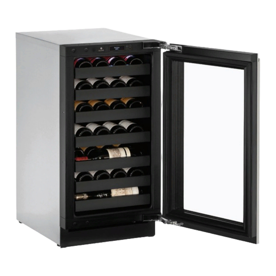
Page 35: Airflow And Product Loading
Do not install the unit behind a door. When properly loaded, your U-Line unit will store up to 31 (750 ml) bottles of wine. Door Removed For Illustration Purposes Internal Air Flow And Unit Ventilation Diagram... -
Page 36: U-Line Wine Guide
YOUNG wine OLD wine LIGHT-BODIED wine FULL-BODIED wine Any step back in quality will be noticed. If a fine wine is tasted prior to a lesser wine, many of the fine wine’s subtle qualities may be missed. U-Line Wine Guide 1... -
Page 37: Common Food And Wine Matches
Great Bordeaux’s may have as much as a 10-year plateau before fading. Myth 4: Wine color does not change with aging. Truth: As red wines age they get lighter in color while whites get darker. U-Line Wine Guide 2... -
Page 38: Common Tasting Terms
Wines can become flat or tired when voids and vacuums are created inside the wine bottle. In order to create voids and vacuums within a liquid, aggressive motion or shaking of the wine bottle would have to occur. U-Line Wine Guide 3... - Page 39 Approximately 45°F (7°C) Sparkling ® Wine Captain Models - A Touch of Elegance In 1985 U-Line was the first North American appliance manufacturer to develop a residential wine storage unit, ® ® the Wine Captain . Each U-Line Wine Captain...
-
Page 40: Recommended Wine Storage
Specially designed horizontal wine racks properly position the bottles so the wine remains in contact with the cork, which ensures the cork does not become dry. U-Line recommends arranging wine bottles as shown in the illustrations below. Racks 1 through 5: Larger diameter bottles may be stored on the shaded racks, illustrated below. -
Page 41: Maintenance
USER GUIDE u-line.com SAFETY • INSTALLATION & INTEGRATION • OPERATING INSTRUCTIONS • • SERVICE MAINTENANCE Cleaning Integrated Models To clean integrated panels, use household cleaner per the EXTERIOR CLEANING cabinet manufacturer’s recommendation. Stainless Models Stainless door panels and handles can discolor when... - Page 42 USER GUIDE u-line.com SAFETY • INSTALLATION & INTEGRATION • OPERATING INSTRUCTIONS • • SERVICE MAINTENANCE NOTICE The drain pan was not designed to capture the water created when manually defrosting. To prevent water from overflowing the drain pan and possibly damaging water sensitive flooring, the unit must be removed from cabinetry.
-
Page 43: Cleaning Condenser
USER GUIDE u-line.com SAFETY • INSTALLATION & INTEGRATION • OPERATING INSTRUCTIONS • MAINTENANCE • SERVICE Cleaning Condenser INTERVAL - EVERY SIX MONTHS To maintain operational efficiency, keep the front grille (plinth strip/base fascia) free of dust and lint, and clean the condenser when necessary. -
Page 44: Wine Rack Installation
USER GUIDE u-line.com SAFETY • INSTALLATION & INTEGRATION • OPERATING INSTRUCTIONS • MAINTENANCE • SERVICE Wine Rack Installation To insert wine racks in the cabinet: 1. Align the left and right rack channels with the tracks in To remove wine racks for cleaning: the cabinet. -
Page 45: Extended Non-Use
If the unit will be exposed to temperatures of 40°F (5°C) or less, the steps above must be followed. For questions regarding winterization, please call U-Line at 414.354.0300. CAUTION Damage caused by freezing temperatures is not covered by the warranty. -
Page 46: Before Calling For Service
• Compressor: The compressor makes a hum or pulsing sound that may be heard when it operates. BEFORE CALLING FOR SERVICE If you think your U-Line product is malfunctioning, read • Evaporator: Refrigerant flowing through an evaporator the CONTROL OPERATION section to clearly understand may sound like boiling liquid. -
Page 47: Checking Product Temperature
12H+ temperature +10° and sealing. Contact properly. For other error codes contact over set point for Customer Care if U-Line Customer Service. over 12 hours. persistent. Product Is Because product in contact with the rear wall (L) (R) Temp Lo... - Page 48 USER GUIDE u-line.com SAFETY • INSTALLATION & INTEGRATION • OPERATING INSTRUCTIONS • MAINTENANCE • SERVICE 6. After 24 hours, check the temperature of the water. If required, adjust the temperature control in a small increment (see CONTROL OPERATION). Causes which affect the internal temperatures of the cabinet include: •...
-
Page 49: Wire Diagram
USER GUIDE u-line.com SAFETY • INSTALLATION & INTEGRATION • OPERATING INSTRUCTIONS • MAINTENANCE • SERVICE Wire Diagram Wire Diagram 1... -
Page 50: Product Liability
The part that caused the damage must be returned to U-Line in its entirety. The part must be clearly labeled with the serial number of the unit it was removed from, the date, and the servicer who removed the part. -
Page 51: Warranty Claims
USER GUIDE u-line.com SAFETY • INSTALLATION & INTEGRATION • OPERATING INSTRUCTIONS • MAINTENANCE • SERVICE Warranty Claims warranty status. We also accept the following information to verify warranty status: The following information defines the parameters for filing a warranty claim: •... - Page 52 Parts U-3045WCINT-60B Item Description U-Line P/N Anti tip bracket w/screws 80-54012-00 Back panel 80-54093-00 Compressor electricals only 80-54017-00 Compressor w/electricals 80-54016-00 Condenser 80-54022-00 Condenser fan w/screws 80-54014-00 Display module 80-54032-00 Door assembly w/o hinges 80-54026-00 Door gasket 80-54003-00 10 Drain pan w/double sided tape...
-
Page 53: Ordering Replacement Parts
Warranty parts will be shipped at no charge after U-Line confirms warranty status. Please provide the model, serial number, part number and part description. Some parts will require color or voltage information. - Page 54 Never use a torch on a fully charged refrigeration system. Never substitute U-Line OEM replacement parts or methods of construction. R-600a must be stored and transported in Technician must observe all federal, state and local laws regarding refrigerants.
- Page 55 USER GUIDE u-line.com SAFETY • INSTALLATION & INTEGRATION • OPERATING INSTRUCTIONS • MAINTENANCE • SERVICE R-600A SPECIFICATIONS/LABELING WARNING R-600a equipped products are labeled (both the unit and the compressor). Only skilled and well trained service technicians permitted to service R-600a equipped products.
-
Page 56: Leak Detection
USER GUIDE u-line.com SAFETY • INSTALLATION & INTEGRATION • OPERATING INSTRUCTIONS • MAINTENANCE • SERVICE Evacuate/reclaim via the piecing pliers to ensure the When re-brazing, the system must be purged with dry system is empty of R-600a before any system work is nitrogen and at least one access point open to the performed. - Page 57 USER GUIDE u-line.com SAFETY • INSTALLATION & INTEGRATION • OPERATING INSTRUCTIONS • MAINTENANCE • SERVICE The low side of the refrigeration system (evaporator, Proper ventilation during service is required. compressor and suction line) must be leak tested with the compressor off (equalized pressure).
-
Page 58: Refrigeration System Diagnosis Guide
USER GUIDE u-line.com SAFETY • INSTALLATION & INTEGRATION • OPERATING INSTRUCTIONS • MAINTENANCE • SERVICE System Diagnosis Guide REFRIGERATION SYSTEM DIAGNOSIS GUIDE System Suction Suction Compressor Condenser Capillary Evaporator Wattage Condition Pressure Line Discharge Tube Normal Normal Slightly below Very hot... -
Page 59: Compressor Specifications
USER GUIDE u-line.com SAFETY • INSTALLATION & INTEGRATION • OPERATING INSTRUCTIONS • MAINTENANCE • SERVICE Compressor Specifications OVERLOAD PROTECTOR STARTING RELAY DANGER Electrocution can cause death or serious injury. Burns from hot or cold surfaces can cause RELAY COVER CAPACITOR serious injury. -
Page 60: Troubleshooting - Extended
DC outputs located on the relay/power board. Included in this section is some diagnostic tips and as always, if additional help is required please contact the U-Line Corp, “Customer Care Facility” at +1.800.779.2547 for assistance. CAUTION Never attempt to repair or perform maintenance on the unit until the main electrical power has been disconnected from the unit. - Page 61 USER GUIDE u-line.com SAFETY • INSTALLATION & INTEGRATION • OPERATING INSTRUCTIONS • MAINTENANCE • SERVICE TROUBLESHOOTING GUIDE Concern Potential Causes Suggested Remedy Not Cooling Compressor overheating Verify proper air flow through condenser (Refer to Airflow/General Information Section). Confirm condenser fan operation (Refer to Airflow/General Information Section).
-
Page 62: Main Control
USER GUIDE u-line.com SAFETY • INSTALLATION & INTEGRATION • OPERATING INSTRUCTIONS • MAINTENANCE • SERVICE MAIN CONTROL Testing The Main Control The main control board is very robust and is rarely the If the main control is suspected of being faulty, the cause of system issues. -
Page 63: Convection Cooling
USER GUIDE u-line.com SAFETY • INSTALLATION & INTEGRATION • OPERATING INSTRUCTIONS • MAINTENANCE • SERVICE Other Suspected Main Control Faults NOTE: If the unit is set to sabbath mode the evaporator fan will no longer respond to the state of the door switch. -
Page 64: Fault System Diagnosis Guide
USER GUIDE u-line.com SAFETY • INSTALLATION & INTEGRATION • OPERATING INSTRUCTIONS • MAINTENANCE • SERVICE FAULT SYSTEM DIAGNOSIS GUIDE Error Solution 1 Solution 2 Solution 3 No Comm Inspect Customer UI and Data Cable (if defective replace entire door) Zone T Open... -
Page 65: Reed Switch
USER GUIDE u-line.com SAFETY • INSTALLATION & INTEGRATION • OPERATING INSTRUCTIONS • MAINTENANCE • SERVICE THERMISTORS REED SWITCH Thermistors are used for various temperature readings. A reed switch is used to monitor door state. When the Thermistors provide reliable temperature readings using a... - Page 66 USER GUIDE u-line.com SAFETY • INSTALLATION & INTEGRATION • OPERATING INSTRUCTIONS • MAINTENANCE • SERVICE Control Operation - Service TO ENTER THE MAIN SERVICE MENU TO GO TO NEXT SUB-MENU ITEM YOU MUST ARROW UP TO “RETURN TO MENU” PRESS AND HOLD...
-
Page 67: Service Menu
USER GUIDE u-line.com SAFETY • INSTALLATION & INTEGRATION • OPERATING INSTRUCTIONS • MAINTENANCE • SERVICE SERVICE MENU The All Errors option keeps record of any system errors. When an error occurs it is recorded to all errors. The In addition to a feature rich customer menu, the 3000... -
Page 68: Relay Status
USER GUIDE u-line.com SAFETY • INSTALLATION & INTEGRATION • OPERATING INSTRUCTIONS • MAINTENANCE • SERVICE Relay Status Description Solution Ambient Check thermistor connection to Thrm thermistor circuit harness for moisture or Select Short shorted. corrosion. Also check connection where thermistor harness attaches to main board. -
Page 69: Input Status
USER GUIDE u-line.com SAFETY • INSTALLATION & INTEGRATION • OPERATING INSTRUCTIONS • MAINTENANCE • SERVICE Relay Toggle Input Status Select Select RETURN TO MENU RETURN TO MENU RELAY TOGGLE INPUT STATUS MULL OFF DOOR OPEN COND OFF IN2 OPEN Down... - Page 70 USER GUIDE u-line.com SAFETY • INSTALLATION & INTEGRATION • OPERATING INSTRUCTIONS • MAINTENANCE • SERVICE 3. Press to scroll through available To access Outputs thermistors. 1. Press to select “Outputs”. To change offsets 4. Press , the selected thermistor will begin to flash.
- Page 71 USER GUIDE u-line.com SAFETY • INSTALLATION & INTEGRATION • OPERATING INSTRUCTIONS • MAINTENANCE • SERVICE Differentials Evap Fan Select Select RETURN TO MENU RETURN TO MENU EVAP FAN DIFFERENTIALS EVAP FAN ON = 1 ZONE = 1°F EVAP FAN OFF = 60...
- Page 72 OFF. Down 1. Press to select “Factory Wi-Fi”. NOTICE Before altering model selection U-Line customer 2. Press service must be notified. Failure to notify customer service will result in voiding of the manufacturer warranty. 3. Press select “OFF”.
-
Page 73: Showroom Mode
USER GUIDE u-line.com SAFETY • INSTALLATION & INTEGRATION • OPERATING INSTRUCTIONS • MAINTENANCE • SERVICE Set Points The Fan Delay menu option allows the modification of fan run times during and after a cooling cycle. In order to allow time for the evaporator to properly cool, the... - Page 74 USER GUIDE u-line.com SAFETY • INSTALLATION & INTEGRATION • OPERATING INSTRUCTIONS • MAINTENANCE • SERVICE To toggle showroom mode 1. Press to select “Showroom Mode”. 2. Press 3. Press to select “Off” and press . “Off” will begin to flash.
- Page 75 USER GUIDE u-line.com SAFETY • INSTALLATION & INTEGRATION • OPERATING INSTRUCTIONS • MAINTENANCE • SERVICE Thermistors Thermistor three (Ambient): Located in the base of the unit (secured to the Thermistors are used for various temperature readings. condenser). It is used to monitor the ambient temperature Thermistors provide reliable temperature readings using a within the base compartment.
- Page 76 USER GUIDE u-line.com SAFETY • INSTALLATION & INTEGRATION • OPERATING INSTRUCTIONS • MAINTENANCE • SERVICE Thermistor Resistance Data Nominal Resistance Temp (F) Temp (C) (OHMS)* 169157 121795 88766 65333 48614 36503 27681 21166 16330 12696 9951 7855 6246 5000 4029...
-
Page 77: Defrost Settings
USER GUIDE u-line.com SAFETY • INSTALLATION & INTEGRATION • OPERATING INSTRUCTIONS • MAINTENANCE • SERVICE Defrost The models below have automatic or frost free design and do not require manual defrosting under normal conditions. Defrost Settings Base Model Variant(s) Compressor Run Time... -
Page 78: Remove Fan And Cover
USER GUIDE u-line.com SAFETY • INSTALLATION & INTEGRATION • OPERATING INSTRUCTIONS • MAINTENANCE • SERVICE Remove Fan and Cover 3. Disconnect power to the unit. CONVECTION COOLING 4. Remove rear cover from unit. This unit is equipped with an advanced convection cooling system. - Page 79 USER GUIDE u-line.com SAFETY • INSTALLATION & INTEGRATION • OPERATING INSTRUCTIONS • MAINTENANCE • SERVICE 13.Remove the 4 screws mounting the fan shroud to the evaporator cover. Air Flow 14.Remove and replace fan. Take special care to properly route fan wire.
-
Page 80: One Year Limited Warranty
One Year Limited Warranty For one year from the date of original purchase, this U-Line product warranty covers all parts and labor to repair or replace any part of the product that proves to be defective in materials or workmanship. For products installed and used for normal residential use, material cosmetic defects are included in this warranty, with coverage limited to 60 days from the date of original purchase.
Need help?
Do you have a question about the U-3045WCINT-60B and is the answer not in the manual?
Questions and answers