Table of Contents
Advertisement
Quick Links
Disclaimer
This manual is provided for user reference only, without legal restraint.
This manual is available for many models. Some functions introduced in the manual
may be not available for some models. Please take the real models as the standard.
This content of this manual is subject to change without prior notice, and the updates
will be added into the new version of this manual.
This manual may contain several technically incorrect places or printing errors, please
feel free to let us know. We will readily improve or update the procedures described in
the manual.
Advertisement
Table of Contents

Related Manuals for e-Line Technology ELI-QUIP-MPTZ3-16XR


Summary of Contents for e-Line Technology ELI-QUIP-MPTZ3-16XR
- Page 1 Disclaimer This manual is provided for user reference only, without legal restraint. This manual is available for many models. Some functions introduced in the manual may be not available for some models. Please take the real models as the standard. This content of this manual is subject to change without prior notice, and the updates will be added into the new version of this manual.
- Page 2 Notes on Safety Please use the specified power supply to connect. Do not attempt to disassemble the camera; in order to prevent electric shock, do not remove screws or covers. There are no user-serviceable parts inside. Please contact the nearest service center as soon as possible if there is any failure.
-
Page 3: Table Of Contents
Contents Chapter 1 Introduction ......................1 Chapter 2 IE Remote Access ....................2 LAN ........................2 2.1.1 Access through IP-Tool ................2 2.1.2 Directly Access through IE ................ 3 WAN ........................5 Chapter 3 Remote Preview ....................8 Chapter 4 Menu Setup ......................10 System Information .................... - Page 4 4.4.8 Home Position ..................22 4.4.9 Wiper Setup ..................... 23 Display Setup ....................... 23 Load Default ......................23 Chapter 5 Remote Configuration .................... 24 System Configuration ................... 24 5.1.1 Basic Information ..................24 5.1.2 Date and Time Configuration ..............24 5.1.3 Local Config ....................
- Page 5 5.6.1 User Configuration .................. 39 5.6.2 Online Video User ................... 41 5.6.3 Block and Allow Lists ................41 Maintenance ......................41 5.7.1 Backup & Restore ..................41 5.7.2 Reboot Device ..................42 5.7.3 Upgrade ....................42 5.7.4 Log ......................43 Chapter 6 Playback ......................
-
Page 6: Chapter 1 Introduction
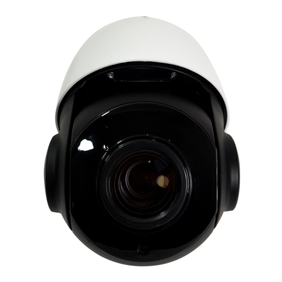
Chapter 1 Introduction This IP speed dome camera is front-end equipment used for video capture. Its digital flip technology makes omni-directional and non-blind-spot monitoring into reality. It utilizes most advanced technologies, such as video encoding and decoding technology, and complies with the TCP/IP protocol, SoC., etc., to ensure this system more stable and reliable. -
Page 7: Chapter 2 Ie Remote Access
Chapter 2 IE Remote Access You may connect IP-Cam via LAN or WAN. Here only take IE browser (6.0) for example. The details are as follows: 2.1 LAN In LAN, there are two ways to access IP-Cam: 1. access through IP-Tool; 2. directly access through IE browser. -
Page 8: Directly Access Through Ie
For example, the IP address of your computer is 192.168.1.4. So the IP address of the camera shall be changed to 192.168.1.X. After modification, please input the password of the administrator and click “Modify” button to modify the setting. The default password of the administrator is “123456”. - Page 9 ① Set the IP address of the PC and make sure the network segment should be as the same as the default settings of the IP camera. Open the network and share center. Click “Local Area Connection” to pop up the following window. Select “Properties”...
-
Page 10: Wan
② Open the IE browser and input the default address of IP-CAM and confirm. The IE browser will download Active X control automatically. ③ After downloading Active X control, the login dialog box will pop up. ④ Input the default username and password and then enter to view. 2.2 WAN ... - Page 11 ③ Go to the router’s management interface through IE browser to forward the IP address and port of the camera in the “Virtual Server”. Router Setup ④ Open the IE browser and input its WAN IP and http port to access. ...
- Page 12 Network connection The setting steps are as follow: ① Go to ConfigNetwork Port menu to set the port number. ② Go to Config Network TCP/IPv4 menu to set the IP address. Check “Use the following IP address” and then input the static IP address and other parameters. ③...
-
Page 13: Chapter 3 Remote Preview
Chapter 3 Remote Preview After you log in, you will see the following window. The descriptions of the icon on the remote preview interface: Icon Description Icon Description Motion alarm indicator Sensor alarm indicator icon icon Original size Open/close audio Appropriate size Snap Auto... - Page 14 Icon Description Icon Description Click it to rotate the dome Click it to rotate the dome diagonally up-left diagonally up-right. Click it to rotate the dome Click it to stop rotating the upwards. dome. Click it to rotate the dome Click it to rotate the dome towards left towards right.
-
Page 15: Chapter 4 Menu Setup
Chapter 4 Menu Setup On the PTZ control panel of IE remote preview interface, call Preset 95 and click . This will take you to see the following main menu setup. The menu setup can be displayed when the resolution of the live is set to 1920×1080. After you go to the main menu interface, you can select the menu by clicking the direction button ( :To select menu by moving up and down. -
Page 16: Auto Pt Flip
System Setup as shown below: 4.2.1 Auto PT Flip Select Auto PT Flip and then click to set up the menu on the right; click button to select On/Off. If “On” is selected, please click button to return to the menu on the left and click button to select Exit. -
Page 17: Date Setup
4.2.4 Date Setup Go to System SetupDate Setup menu as shown below: ① Set the date and time by clicking the direction button. ② Select STORE to save the setting. 4.2.5 Title Setup Go to System SetupTitle Setup as below: You can click direction button to set the title and then save the setting. -
Page 18: New Password And Change Password
4.2.7 New Password and Change Password New Password Enter the password by clicking button. Numbers from 0 to 9 are available. The password should be 6 characters. Empty password is invalid when you set the new password. ... -
Page 19: Camera Control
4.3.1 Camera Control After you select Camera Control, you will see the following menu. 【BLC】 :When the background light is so stronger that the foreground is dark, the brightness of the whole image will improve thereby enhancing the visibility of the foreground image if the BLC function is enabled. - Page 20 AE Setup Go to AE Setup menu as shown below: 【AE MODE】: Auto, Bright, Shutter, IRIS and Manual are optional. 【Brightness】 : Range from 0(darkest)~20(brightness). It is available only when bright mode is selected. 【Shutter】 :The lower the value of camera shutter is, the brighter the image is. It is available only when the shutter or manual mode is selected.
-
Page 21: Lens Setup
AGC The larger the number is, the higher the brightness and the more the noises of the image are. Image Flip MIRR: Turn over the image left or right. FLIP: Turn over the image up or down. ... -
Page 22: Video Format
Auto:Camera will automatically switch the mode between day and night as per the ambient illumination. Night:The camera will be night mode at all time. You’d better use this mode at night. Day: The camera will be day mode at all time. You’d better use this mode in daytime. ... -
Page 23: Cruise Setup
② Select the preset number. ③ Go to Edit CUR Preset interface as below: Press iris – to switch menu mode and PTZ mode. And then set the position of the preset ④ by clicking the direction buttons. ⑤ Set the title by clicking button. -
Page 24: Grouping Setup
Set the preset and time. The preset ranges from 001 to 255 and the dwell time is from 05s to 240s. ③ Run the current cruise. The camera will automatically keep running according to the cruise you set until new command is received. The corresponding operating information will display on the screen when the camera is running. -
Page 25: Track Setup
By dividing 24 hours into several periods and appointing different commands for each period, the camera system will automatically execute the commands according to the set time if there is no operation. Setting Steps: ① Enable the task. ② Set the task. Time Format: Start Time –... -
Page 26: Alarm Setup
operation progress can be realized by running track. Setting Steps: ① Choose the track number. Edit the track. Enter the track setting menu. Click “Iris –“ to start recording track. ② Control the dome movement by direction buttons and then save the setting. Each track can record up to 180s. -
Page 27: Privacy Mask
Note: If the dome is on the menu state on an alarm, any command is negative. 4.4.7 Privacy Mask Go to the Main Menu Dome Function Privacy Mask menu as below: 【Mask NO.】 :Set the current mask area. 8 mask areas can be set at most. 【Mask Color】... -
Page 28: Wiper Setup
4.4.9 Wiper Setup Some models may not support this function. Go to Main MenuWiper Setup as shown below. ① Set the speed level and run time. Call “START” to enable wiper function. ② 4.5 Display Setup You can enable title display and time display if you need. 4.6 Load Default There are three menus, including master reset, master clear and system reboot. -
Page 29: Chapter 5 Remote Configuration
Chapter 5 Remote Configuration 5.1 System Configuration The “System configuration” includes four sub-menus: Basic Information, Date and Time, Local Config and SD Card. 5.1.1 Basic Information In the Basic Information interface, you can check the relative information of the device. 5.1.2 Date and Time Configuration Go to ConfigSystemDate and Time. -
Page 30: Local Config
5.1.3 Local Config Go to ConfigSystemLocal Config. You can set the storage path of the captured pictures and video records. 5.1.4 SD Card Go to ConfigSystemSD Card. In the above interface, you can check the capacity, used capacity, remaining capacity and state of the SD card. -
Page 31: Video / Audio Configuration
5.2.1 Video / Audio Configuration The following interface will be displayed by clicking ConfigImageVideo/Audio. In this interface, you can set the resolution, frame rate, bitrate type, video quality and so on subject to the actual network condition. To set the audio encoding and audio type, please select the audio tab. 5.2.2 OSD Configuration Go to ConfigImageOSD menu to display the interface as shown below: You may set time stamp, device name and OSD here. -
Page 32: Ptz Configuration
Many parameters of the camera can be set in above sub-menu, such as Color, Brightness, Sharpness, 3D DNR, Fog, Day Night Mode and so on. Please refer to Chapter 4.3 for more detail. 5.3 PTZ Configuration 5.3.1 PTZ and Password Setting ... -
Page 33: Load Default
keyboard control. Password Setting If the password is set, you must input the password every time you go to the menu of the PTZ by calling preset NO. 95. Go to ConfigPTZSettingOthers. You can set the password of the PTZ menu. 5.3.2 Load Default It includes the function of reset, clear and restart. - Page 34 Trigger Snap: If selected, the system will snap images on an alarm and save them in SD card. Trigger Email: If the email and attach picture checkbox is checked (Email address shall be set first in the Mail config interface), the triggered snap pictures and event will be sent into those addresses.
-
Page 35: Alarm Input
Week schedule Set the alarm time from Monday to Sunday for alarm everyday in one week. The lengthwise means one day of a week; the rank means 24 hours of a day. Green means selected area. Blank means unselected area. “Add”: Add the schedule for a special day. -
Page 36: Alarm Out
Set the alarm type, alarm holding time and sensor name. Enable alarm. Set alarm trigger options. The setting steps are the same with that of motion detection. Please refer to motion detection chapter for details. Click “Save” to save the settings. If there are many sensors, you may use “Copy”... -
Page 37: Alarm Server
2. Select alarm holding time and alarm name at the “Alarm Holding Time” and “Alarm Out” pull down list box respectively. 3. Click “Open” to trigger alarm output. Click “Close” to stop alarm output. 4. Press the “Save” button to save the settings. 5.4.4 Alarm Server ... -
Page 38: Port
You can choose either way of the network connection. If you use PPPoE to connect internet, you will get a dynamic WAN IP address. This IP address will change frequently. You may use the function of IP change notification. Trigger Email: when the IP address of the device is changed, a new IP address will be sent to the appointed mailbox automatically Trigger FTP: when the IP address of the device is changed, a new IP address will be sent to FTP server. -
Page 39: Ddns Configuration
1. Check “Enable”. 2. Check the IP address and port of the transfer media server in the ECMS/NVMS. Then enable the auto report in the ECMS/NVMS when adding a new device. Next, input the remaining information of the device in the ECMS/NVMS. After that, the system will auto allot a device ID. -
Page 40: Snmp
Create domain name. After you successfully request your domain name, you will see your domain in the list. 3. Input the username, password, domain you apply for in the DDNS configuration interface. 4. Click “Save” button to save the settings. 5.5.5 SNMP To get camera status, parameters and alarm information and remotely manage the camera, you can set the SNMP function. -
Page 41: Rtsp
3. Set the “Read SNMP Community”, “Write SNMP Community”, “Trap Address”, “Trap Port” and so on. Please make sure the settings are the same as that of your SNMP software. Note: Please use the different version in accordance with the security level you required. The higher the version is, the higher the level of the security is. -
Page 42: Upnp
1. Select “Enable”. 2. RTSP Port: Access port of the streaming media. The default number is 554. 3. RTSP Address: The RTSP address you need to input in the media player. 4. Check “Enable anonymous viewer login…”. 5.5.7 UPnP If you enable this function, you can quickly access the camera via LAN and you don’t need to configure the port mapping when the camera is connected to the WAN via the router. -
Page 43: Ftp
Sender Address: sender’s e-mail address; User name and password: sender’s user name and password; SMTP Address: The SMTP IP address or host name. Select the secure connection type at the Secure Connection pull down list according to user’ actual needs; SMTP Port: The SMTP port. -
Page 44: Security Configuration
Server Name:The name of the FTP. Server Address: The IP address or domain name of the FTP. Port: The port of the FTP. Use Name and Password: The username and password are used to login the FTP. Upload Path: The path of uploading the files. Send Pictures: If enabled, the captured pictures will be uploaded to FTP. - Page 45 2. Input user name in “User Name” textbox. 3. Input letters or numbers in “Password” and “Confirm Password” textbox. 4. Choose the use type. 5. Input the MAC address of the PC in “Binding MAC address” textbox. After binding physical address to the IP-CAM, you can access the device on this PC only. If the MAC address was “00:00:00:00:00:00”...
-
Page 46: Online Video User
2. Click “Delete” button to delete the user. Note: The default super administrator cannot be deleted. 5.6.2 Online Video User Go to ConfigSecurityOnline Video User. You can view the user who is viewing the live video. 5.6.3 Block and Allow Lists Go to ConfigSecurityBlock and Allow Lists. -
Page 47: Reboot Device
Import & Export Setting: You can import or export the setting information from PC or to device. 1. Click “Browse” to select save path for import or export information on PC. 2. Click “Import Setting” or “Export Setting” button. ... -
Page 48: Log
5.7.4 Log To query and export log 1. Go to ConfigMaintenanceOperation Log. 2. Select the main type, sub type, start and end time. 3. Click “Query” to view the operation log. 4. Click “Export” to export the operation log. You can view the run log by clicking ConfigMaintenanceRun Log. -
Page 49: Chapter 6 Playback
Chapter 6 Playback 6.1 Photo Search Click “Search” icon to search the photos saved in the SD card. 1. Set time: Select date and choose the start and end time. 2. Choose “Motion” or “Sensor”. 3. Click “Search” button to search the picture. 4. -
Page 50: Video Search
Item Buttons Explanations Close: Select certain picture and click this button to close this picture. Close all: Click this button to close all pictures viewing. Save: Click this button to select the save path of the picture file on the PC for saving the current picture. Save all: Click this button to select the save path of the picture files on PC for saving all pictures. - Page 51 Choose the date and the start time and end time and then click “Search” button to search the record files. Double click the record file to play the record. The descriptions of the buttons on the playback interface are as follows. Button Description Play button.
-
Page 52: Chapter 7 Q & A
Chapter 7 Q & A 1. Q: I forget the password. How can I do? Reset the system to the factory default setting or contact the dealer. Default IP: 192.168.226.201 User name: admin Password: 123456 2. Q:The devices can’t connect through IE browser. Why? ①... - Page 53 Fig 4-1 Fig 4-2 ④ Then click OK to finish setup. Other plug-ins or anti-virus blocks ActiveX. Please uninstall or close them. 5. Q:Why does the device fail to sound? The audio input device is not connected. Please connect and try again. The audio function is not enabled at the corresponding channel.
-
Page 54: Appendix Preset Description
Appendix Preset Description Call NO.90 Preset Run track 1 Call NO.91 Preset Run cruise 1 Call NO.92 Preset Run cruise 2 Call NO.93 Preset Run cruise 3 Call NO.94 Preset Run cruise 4 Call Preset Call NO.95 Preset OSD menu Call NO.97 Preset Enable random scan Call NO.99 Preset...
Need help?
Do you have a question about the ELI-QUIP-MPTZ3-16XR and is the answer not in the manual?
Questions and answers