Table of Contents
Advertisement
Quick Links
Issue 2017-04-10
Product Description
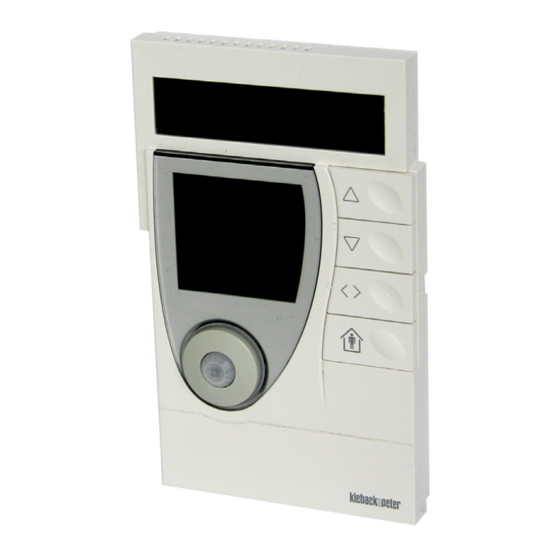
RPW414P-FTL room control module
Room control module with room humidity/temperature sensor, SolarRadio
technology, integrated bidirectional EnOcean wireless interface and an
algorithm for self-learning of utilization time profiles/heating profiles in rooms.
Application
Solar-powered, self-learning room control module with LCD and smart commu-
nication management.
For measuring room humidity and temperature, independent generation of utili-
zation time profiles and their continuous dynamic adjustment/optimization and
for wireless transmission of measured values.
Operating elements for manually changing the comfort mode or economy mode
status to adjust the room setpoint.
Together with the MD15-FTL wireless small actuator, the RPW414P-FTL room
control module constitutes a functional unit for easy room temperature control.
The following EnOcean Equipment Profiles (EEP) are supported:
■
EEP D2-10-30 *
* You can find information about the protocol description on the EnOcean
Technology website http://www.enocean-alliance.org/en/enocean_standard/
Änderungen vorbehalten - Contents subject to change - Sous réserve de modifications - Reservado el derecho a modificación - Wijzigingen
voorbehouden - Con riserva di modifiche - Innehåll som skall ändras - Zmeny vyhradené - Změny vyhrazeny - Zmiany zastrzeżone - Возможны
изменения - A változtatások jogát fenntartjuk -
Kieback&Peter GmbH & Co. KG
Tempelhofer Weg 50, 12347 Berlin/Germany
Telefon: +49 30 60095-0, Telefax: +49 30 60095-164
www.kieback-peter.de, info@kieback-peter.com
Datasheet 1.10-65.040-01-EN
RPW414P-FTL
+
A
Advertisement
Table of Contents

Related Manuals for Kieback&Peter RPW414P-FTL


Summary of Contents for Kieback&Peter RPW414P-FTL
- Page 1 Operating elements for manually changing the comfort mode or economy mode status to adjust the room setpoint. Together with the MD15-FTL wireless small actuator, the RPW414P-FTL room control module constitutes a functional unit for easy room temperature control. The following EnOcean Equipment Profiles (EEP) are supported: ■...
-
Page 2: Table Of Contents
Indicators on the display ..........................10 Commissioning ............................... 11 Switching the device on/off ..........................11 “Test installation location” function........................12 Teaching in the MD15-FTL radio partner on the RPW414P-FTL..............13 Mounting ................................14 Removal ................................16 Operating level ..............................16 Setting the initial display.......................... -
Page 3: Important Information On Product Safety
Important Information on Product Safety Safety instructions This data sheet contains information on installing and commissioning the product “RPW414P-FTL”. Read this product description prior to installation, commissioning or operation. No previous special knowledge is required to commission and operate this product. - Page 4 The operating modes described here apply solely for the self-learning room controller consisting of: - MD15-FTL wireless small actuator and - RPW414P-FTL room control module. Other radio partners, e.g. gateways can generate other functions. Comfort mode: Operating mode for a room that is in use (usage status: “Present”). The setpoint for comfort mode is used as the basis for control.
-
Page 5: Item
Product Description RPW414P-FTL Item RPW414P-FTL Room control module with room humidity/temperature sensor, SolarRadio technol- ogy and integrated bidirectional EnOcean wireless interface. Automatic determination of the utilization time profile/heating profile in the room for automatic control of comfort mode and economy mode. -
Page 6: Dimensions
Datasheet 1.10-65.040-01-EN Issue 2017-04-10 RPW414P-FTL Product Description Mounting Flexible mounting using screws or adhesive Maintenance Maintenance-free Weight 0.22 kg Dimensions WxHxD in mm: 90 x 153.7 x 26.7 Dimensions 10,5 91,6 R 30,0 90,0 19,7 Radio Interface The radio communication with the radio partner is cyclical, bidirectional and includes an intelligent synchronization process. -
Page 7: Installation
Product Description RPW414P-FTL Installation CAUTION This product description describes the specific settings and functions of the RPW414P-FTL room control module. In addition to these instructions, the product description of the radio partner must also be observed. General installation instructions It is not always possible to freely select the installation location of devices which communicate wirelessly, as radio data transmission is influenced to a greater or lesser extent by structural or spatial factors. - Page 8 1,5 m ■ As a result of the autonomous operation and wireless installation of RPW414P-FTL, the selected installation location can be changed and optimized at any time without additional effort. The installation location must have sufficient lighting; using the device in unlit rooms (such as interior kitchens/bathrooms) shortens long-term functionality.
-
Page 9: Operating And Control Elements
To select the display or menus Occupancy button -To switch between comfort mode/economy mode, see page 17 - To switch the RPW414P-FTL on and off (together with the Setting button), see page 11 - For setting functions Setting button - To switch the room control module on (together... -
Page 10: Indicators On The Display
Datasheet 1.10-65.040-01-EN Issue 2017-04-10 RPW414P-FTL Product Description Indicators on the display 06 07 08 09 10 11 12 Item Icon/display Explanation Time The information field displays the time (HH:mm) Information field Display of the room temperature, room humidity, date, time... -
Page 11: Commissioning
Issue 2017-04-10 Datasheet 1.10-65.040-01-EN Product Description RPW414P-FTL Commissioning Switching the device on/off (01) Setting button (02) Occupancy button ■ Switching on The device is delivered in storage mode (switched off). All functions are deactivated and the device does not consume any power. The energy storage unit has been fully charged at the factory for initial commissioning. -
Page 12: Test Installation Location" Function
Datasheet 1.10-65.040-01-EN Issue 2017-04-10 RPW414P-FTL Product Description “Test installation location” function The room control module provides assistance in selecting the optimum installation location. This function is active after switching on the device (see the “Switching the Device On/ Off” section page 11), provided a radio partner has not been registered (for a maximum of 15 minutes). -
Page 13: Teaching In The Md15-Ftl Radio Partner On The Rpw414P-Ftl
(two long tones), this means that an error has occurred and registration has failed. Start the teach-in process again. The wireless small actuators are registered on the RPW414P-FTL. The room control module now starts to learn the individual utilization time profile. -
Page 14: Mounting
Datasheet 1.10-65.040-01-EN Issue 2017-04-10 RPW414P-FTL Product Description Default utilization time profile: Room used: 6:00 AM - 8:00 PM, comfort temperature Room unused: 8:00 PM - 6:00 AM, economy temperature NOTE Once the procedure is complete, it is not possible to add an additional wireless small actuator. - Page 15 Issue 2017-04-10 Datasheet 1.10-65.040-01-EN Product Description RPW414P-FTL Wall mounting - Flexible screw mounting (1) Bar (2) Adhesive numbers Wall mounting - Flexible adhesive mounting with double-sided transparent adhesive strips NOTE For a permanent connection, remove any dust and grease from the adhesive surface on the wall mount and the wall.
-
Page 16: Removal
Datasheet 1.10-65.040-01-EN Issue 2017-04-10 RPW414P-FTL Product Description Removal Operating level Setting the initial display ► Briefly pressing the selector button “ ”, enables you to select the following displays: ■ Room temperature ■ Relative room humidity, see example ■ Date ■... -
Page 17: Manually Switching Between Comfort And Economy Mode
Issue 2017-04-10 Datasheet 1.10-65.040-01-EN Product Description RPW414P-FTL Manually switching between comfort and economy mode ► You can manually switch between comfort mode and economy mode and vice versa by pressing the “Occupancy button”. This is displayed by the comfort mode or economy mode icons. -
Page 18: Automatically Switching Between Comfort And Economy Mode
Datasheet 1.10-65.040-01-EN Issue 2017-04-10 RPW414P-FTL Product Description Automatically switching between comfort and economy mode Automatic switching between comfort or economy mode is performed according to the utilization profile learned. The utilization profile is generated automatically, and is continuously and dynamically adjusted and optimized. -
Page 19: Menu Level
Issue 2017-04-10 Datasheet 1.10-65.040-01-EN Product Description RPW414P-FTL Menu level NOTE If no settings are made within approx. 5 seconds, the individual setting functions are exited and saved as required. Config menu The following functions are available in the Config menu: ■... -
Page 20: Setting The Time And Date
Datasheet 1.10-65.040-01-EN Issue 2017-04-10 RPW414P-FTL Product Description When vacation mode is active, the room control module is in economy mode and control is based on the setpoint for vacation mode, see page 24. The display also shows the (house without little man) symbol. -
Page 21: Setting The 12/24 Hour Display
Issue 2017-04-10 Datasheet 1.10-65.040-01-EN Product Description RPW414P-FTL Once the last value for the day has been entered, this is indicated by a moving line on the display. The time and date settings are complete and are saved. The display then switches to the initial display. -
Page 22: Switching The Temperature Scale °C/°F
Datasheet 1.10-65.040-01-EN Issue 2017-04-10 RPW414P-FTL Product Description Switching the temperature scale °C/°F ► Hold down the “Occupancy button” for 5 seconds. The text “Menu” briefly appears on the display, followed by “SETP”. ► Release the “Occupancy button”. ► Briefly press the “Occupancy button” repeatedly or the “... -
Page 23: Info Menu
Issue 2017-04-10 Datasheet 1.10-65.040-01-EN Product Description RPW414P-FTL Info menu The following information is displayed in the Info menu: ■ Status message ■ Display of the taught-in radio partners – Wireless address of the taught-in radio partners – Position indication of the taught-in wireless small actuators –... -
Page 24: Setpoint Menu - Adjusting The Setpoints
Datasheet 1.10-65.040-01-EN Issue 2017-04-10 RPW414P-FTL Product Description Setpoint menu – Adjusting the setpoints The setpoints for comfort mode, economy mode and vacation mode are set here. ► Hold down the “Occupancy button” for 5 seconds. The text “Menu” briefly appears on the display, followed by “SETP”. -
Page 25: Service Level
► Hold down the “Occupancy button” for about 5 seconds and the “Teach in the MD15-FTL radio partner” function will run (see the “Teaching in the MD15-FTL radio partner on the RPW414P-FTL” section on page 13). Page 25 / 32... - Page 26 Datasheet 1.10-65.040-01-EN Issue 2017-04-10 RPW414P-FTL Product Description Teaching in an EnOcean system gateway ► Briefly press the “Occupancy button” repeatedly or the “ ” button to select the “GATE” function. ► Hold down the “Occupancy button” for about 5 seconds and the “Teach in an EnOcean system gateway”...
- Page 27 Issue 2017-04-10 Datasheet 1.10-65.040-01-EN Product Description RPW414P-FTL Restoring default settings and switching off the control module (see also page 19) ► Briefly press the “Occupancy button” repeatedly or the “ ” button to select the “RES” function. ► Hold down the “Occupancy button” for about 5 seconds and the “Restore default settings and switch off room control module”...
-
Page 28: Messages
Datasheet 1.10-65.040-01-EN Issue 2017-04-10 RPW414P-FTL Product Description Messages Status messages Icon/display State Explanation Antenna Radio connection functioning properly; Er00 is displayed in the Info menu InSt “Test installation location” evaluation function is active Antenna Flashes Possible to register wireless small actuators Antenna Radio connection partly interrupted (>... - Page 29 “Battery” icon appears on the display if the charge state drops below 30%. NOTE Charge the energy storage unit by placing the RPW414P-FTL in a source of light for two hours (day light or artificial light, but not direct sun light).
-
Page 30: Malfunction Messages
Press the “Occupancy button” briefly to quit this display. Malfunction messages Icon/display State Explanation Antenna Transmission function on the RPW414P-FTL malfunction- Er08 Er03 Synchronization on the RPW414P-FTL malfunctioning Transmission function malfunctioning The radio connection is continuously monitored. If a transmission function malfunction is detected in the room control module, the “... - Page 31 Issue 2017-04-10 Datasheet 1.10-65.040-01-EN Product Description RPW414P-FTL System time The internal system time of the room control module is monitored constantly. If a system time malfunction is detected in the room control module, the “ Er03” icon appears on the display.
- Page 32 Datasheet 1.10-65.040-01-EN Issue 2017-04-10 RPW414P-FTL Product Description Page 32 / 32...
Need help?
Do you have a question about the RPW414P-FTL and is the answer not in the manual?
Questions and answers