Table of Contents
Advertisement
Quick Links
Advertisement
Table of Contents

Subscribe to Our Youtube Channel
Related Manuals for Weil-McLain UO-3 CV


Summary of Contents for Weil-McLain UO-3 CV
- Page 1 R02 01/09...
- Page 2 AF/AFG AF/AFG Oil Burner Manual Oil Burner Manual Potential for Fire, Smoke and Asphyxiation Hazards Incorrect installation, adjustment, or misuse of this burner could result in death, severe personal injury, or substantial property damage. To the Homeowner or Equipment Owner: Please read and carefully follow all instructions provided in this manual regarding your responsibilities in caring for your heating...
-
Page 3: Table Of Contents
Hazard Def nitions and Owner’s Information Information To Be Used Only By Qualif ed Service Technicians General Information ... 4 Table 1 Burner Specifi cation ... 4 Notice Special Requirements ... 5 Table 2 Air Tube Combination (ATC) Codes …………………………………………………………..5 Inspect/Prepare Installation Site Inspect Chimney or Direct Vent System ... - Page 4 Hazard Defi nitions Indicates a hazardous situ- DANGER ation, which, if not avoided, will result in death or serious injury. Indicates a hazardous WARNING situation, which, if not avoided, could result in death or serious injury. Indicates a hazardous CAUTION situation, which, if not avoided, could result in minor or moderate injury.
-
Page 5: General Information
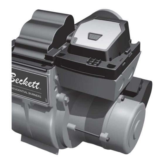
General Information To the Owner: Thank you for purchasing a Beckett burner for use with your heating appliance. Please pay at- tention to the Safety Warnings contained within this instruction manual. Keep this manual for your records and provide it to your qualifi ed service agency for use in professionally setting up and maintaining your oil burner. -
Page 6: Notice Special Requirements
Table 2 – Air Tube Combination (ATC) codes Firing Head Static Ven- Rate plate turi (gph) size (min- (inches) 4-1/2 max) 0.50-0.75 3-3/8U None AF44XR 0.75-1.25 2-3/4U None AF44XN 0.85-1.35 2-3/4U None AF44WH 0.85-1.65 2-3/4U None AF44YB 1.10-2.00 2-3/4U None AF44XO 1.65-2.50 2-3/4U... -
Page 7: Inspect/Prepare Installation Site
Inspect/Prepare Installation Site Inspect Chimney or Direct Vent System Fire, Smoke & Asphyxia- WARNING tion Hazard Carefully inspect the chimney or exhaust vent system. Make sure it is properly sized and in good work- ing condition. Follow the instructions supplied by the appliance manufacturer. -
Page 8: Combustion Air Supply
Combustion air supply Adequate Combustion WARNING and Ventilation Air Supply Required Failure to provide adequate air supply could seriously affect the burner performance and re- sult in damage to the equipment, asphyxiation, explosion or fi re hazards. The burner cannot properly burn the fuel if it is not supplied with a reliable combustion air source. -
Page 9: Prepare The Burner
Inspect/Prepare Installation Site Prepare the Burner Low Firing Rate Baff e The AFG Low Firing Rate Baffl e (LFRB) reduces the air fl ow and pressure. The LFRB is sometimes used for fi ring rates under 1.00 gph as listed in Table 4. -
Page 10: Check/Adjust Electrodes
If the nozzle is already installed, remove the noz- zle line assembly to verify that the nozzle size and spray pattern are correct for the application (per ap- pliance manufacturer’s information). Verify that the electrode tip settings comply with Figure 3. If the nozzle is not installed, obtain a nozzle from the manufacturer, having the capacity and spray angle specifi... -
Page 11: Check/Adjust 'Z' Dimension - F Heads
Prepare the Burner Check/Adjust ‘Z’ Dimension for ‘F’ Heads Figure 4. 1-3/8” Adjust the ‘Z’ dimen- WARNING sion to the required specif cation. Incorrect Adjustments could cause combus- tion problems, carbon deposition from fl ame impingement, heavy smoke generation and fi... -
Page 12: Check/Adjust 'Z' Dimension - L & V Heads
Check/Adjust ‘Z’ Dimension - L1 & Figure 5. L2 Heads L1/L2 heads (see Table 7 and Figure 3 for dimensions) See fi gure above. The important “Z” dimension is the distance from the leading edge of the head to the end of the air tube. This distance for L1 &... -
Page 13: Installing The Oil Tank & Supply System
Mount burner on appliance Figure 7. – Mounting Burner in Appliance If space between burner air tube and opening exceeds 1/2 inch, pack burner opening with ce- ramic fiber refractory. Tilt down 2 Installing the Oil Tank and Supply System Oil Leak and Fire Hazard WARNING Install the oil tank following applicable stan-... -
Page 14: Wire Burner
Oil Supply Pressure CAUTION Control Required Damage to the fi lter or pump seals could cause oil leakage and a fi re hazard. The oil supply inlet pressure to the burner can- not exceed 3 psig. Insure that a pressure limiting device is installed in accordance with the latest edition of NFPA 31. -
Page 15: Burner Control
Burner Controls GeniSys Model 7505 Control Fire or Explosion Hazard Can cause severe injury, death, or property damage. The control can malfunction if it gets wet, leading to accumulation of oil or explosive oil vapors. Never install where water can fl ood, drip or condense on the control. -
Page 16: Typical Burner Sequence Of Operation For Genisys 7505 Control
Typical Burner Sequence of Operation for GeniSys 7505 Control. Refer to the appliance manufacturer’s wiring diagram for actual specifi cations. Valve-on delay Motor-off delay Standby: The burner is idle, waiting for a call for heat. Valve-On Delay: The igniter and motor are on while the control delays turning on the oil solenoid valve for the programmed time. -
Page 17: Reset Button Operation
Burner Controls Figure 1 1a. – Interrupted ignition, valve-on delay only (no motor-off delay) SAFETY AND OPERATING LIMITS THERMOSTAT IGNITER MOTOR OIL VALVE CAD CELL Reset Button Operation Table 2 explains what action the control will take when the reset button is pressed for different lengths of time during the various burner operating states. -
Page 18: Typical Burner Sequence Of Operation For R7184P Control
Typical Burner Wiring & Burner Sequence of Operation for R7184P Control. Refer to the appliance manufacturer’s wiring diagram for actual specifi cations. 1. STANDBY. The burner is idle, waiting for a call for heat. When a call for heat is initiated, there is a 3- 10 second delay while the control performs a safe start check. -
Page 19: Start-Up Burner/Set Combustion
Wire burner Some Thermostats Are Polar- NOTICE ity Sensitive. Reversed polarity could cause erratic cycling of the burner control. Connect the wire from the R thermostat to the TR terminal on the control. Connect the wire from the W terminal on the thermostat to the TW terminal on the control. -
Page 20: Startup/Checkout
Startup / Checkout Explosion and Fire Hazard WARNING Failure to follow these instructions could lead to equipment malfunc- tion and result in heavy smoke emission, soot-up, hot gas puff- back, fi re and asphyxiation hazards. Do not attempt to start the burner when excess oil has accumulated in the appliance, the ap- pliance is full of vapor, or when the combustion chamber is very hot. -
Page 21: Perform Regular Maintenance
Perform regular maintenance Step 4: Recheck smoke level. It should be Zero. • This procedure provides a margin of reserve air to accommodate variable conditions. • If the draft level has changed, recheck the smoke and CO the burner if necessary Once combustion is set, tighten all fasteners on air band, air shutter and head adjusting plate or es- cutcheon plate. - Page 22 Replace the blower wheel: Turn off all power to the burner before servic- ing. Disconnect the burner motor wires. Remove the bolts securing the motor to the burner housing. Remove the motor and blower wheel. Remove the existing blower wheel. Referring to the fi...
- Page 24 For best performance specify genuine Part No. Description Burner Housing Assembly Specify* Air Band - Specify # of slots Specify* Air Shutter - Specify # of slots 21807U Valve Cordset Not Shown 21887U PD Timer Delay Cordset 2184404U CleanCut Pump 5394 Copper Oil Line - 8”...
-
Page 25: Beckett Limited Warranty Information
For Residential, Commercial and Specialty Burners The R. W. BECKETT CORPORATION (“Beckett”) warrants to persons who purchase its Beckett burners from Beckett for resale or for incorporation into a product for resale (“Customers”) that its equipment is free from defects in material and workmanship under normal use and service for 60 months from the date of manufacture for Residential Burners and 18 months from the date of manufacture for Commercial and Specialty Burners.
Need help?
Do you have a question about the UO-3 CV and is the answer not in the manual?
Questions and answers