Table of Contents
Advertisement
Quick Links
Advertisement
Table of Contents

Related Manuals for Leonton PG5-0501-SFP-24 Series


Summary of Contents for Leonton PG5-0501-SFP-24 Series
- Page 1 Leonton PG5-0501-SFP-24 Series (PG5-0501-SFP-24 / PG5-0501-SFP-24-T) User Manual...
- Page 2 Disclaimer Leonton Technologies, Co. Ltd. provides this manual without warranty of any kind, expressed or implied, including but not limited to the implied warranties of merchantability and fitness for a particular purpose.
- Page 3 This is a Class-A product. In a domestic environment this product may cause radio interference in which case the user may be required to take adequate measures. This document is the current official release manual. Please check our website (www.leonton.com) for any updated manual or contact us by e-mail (sales@leonton.com).
-
Page 4: Table Of Contents
Contents Overview ........................1 Software Features ....................1 Hardware Features ....................2 Package Contents ....................3 Safety Precaution ....................3 Hardware Description ....................4 Physical Dimensions ....................4 Front Panel ......................5 Top View ....................... 5 LED Indicators......................6 Ethernet Ports ....................... 7 Cabling ........................ -
Page 5: Overview
Overview This series is rated IP30 and installation by DIN Rail. Each unit of this industrial gigabit managed Ethernet switch series has 4* 10/100/1000TX with 4 IEEE 802.3at compliant ports (30W/port) and 1 dual-rate (100/1000) SFP slots, suitable for applications that require high bandwidth and long distance communication. -
Page 6: Hardware Features
PoE ports weekly power scheduling Port Configuration Port Status, Statistics, Monitoring, Mirroring, Security, and Rate Limiting Event Handling Event notification by Email/Syslog: System Cold Start, port link-up/down Fault Alarm Relay Output for power failure, port link-down/broken Software Upgrade ... -
Page 7: Package Contents
Package Contents 1 - PG5-0501-SFP-24(-T) product 1 – User manual CD 2 - Wall mounting brackets and screws 1 - RJ45 to DB9 Serial Console cable Safety Precaution Attention If the DC voltage is supplied by an external circuit, please use a protection device on the power supply input. -
Page 8: Hardware Description
Hardware Description Physical Dimensions Figure 2.1, below, shows the physical dimensions of PG5-0501-SFP-24 series. (W x D x H) is 54mm x 99mm x 142mm Figure 2.1: PG5-0501-SFP-24 Series Physical Dimensions... -
Page 9: Front Panel
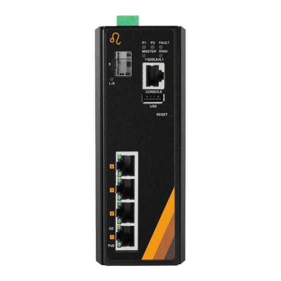
Figure 2.2: The Front Panel of PG5-0501-SFP-24 Series Top View Figure 2.3, below, shows the top panel of the PG5-0501-SFP-24 series switch that is equipped with one 6-pin removal terminal block connector for dual DC power inputs (12~55VDC). Figure 2.3: Top Panel View of PG5-0501-SFP-24 Series... -
Page 10: Led Indicators
LED Indicators There are LED light indicators located on the front panel of the industrial Ethernet switch that display the power status and network status. Each LED indicator has a different color and has its own specific meaning, see below in Table 2.4. Color Description Power input 1 is active... -
Page 11: Ethernet Ports
Table 2.4: LED Indictors for PG5-0501-SFP-24 Series Caution: "P1/P2" is the abbreviation for "Power 1/Power 2", "L" is for "Link", and "A" is for "Activity", “GE” is for “Gigabit Ethernet Port”. Ethernet Ports RJ-45 Ports (Auto MDI/MDIX) The RJ-45 ports are auto-sensing for 10Base-T, 100Base-TX or 1000Base-T devices connections. -
Page 12: Cabling
1000BASE-T RJ-45 Pin Assignments (Table 2.6) Crossover Cable Straight Through Cable Pin Number / Signal Pin Number / Signal Pin Number / Signal Pin Number / Signal 1 / TP0+ 3 / TP1+ 1 / TP0+ 1 / TP1+ 2 / TP0- 6 / TP1- 2 / TP0- 2 / TP1-... - Page 13 Figure 2.7: Transceiver to the SFP Module Figure 2.8: Transceiver Inserted Step 2 Insert the fiber cable of the LC connector into the transceiver as shown below in Figure 2.9. Figure 2.9: LC Connector to the Transceiver To remove the LC connector from the transceiver, please follow the steps shown below: Step 1 Press the upper side of the LC connector from the transceiver and pull it out to release as shown below in Figure 2.4...
-
Page 14: Wiring The Power Inputs
Figure 2.4: Remove LC Connector Step 2 Push down the metal clasp and pull the transceiver out by the plastic part as shown below in Figure 2.5 Figure 2.5: Pull Out from the SFP Module Wiring the Power Inputs Caution: Please follow the below steps to insert the power wire. Step 1 Insert the positive and negative wires into the PWR1 (V1+, V1-) and PWR2 (V2+, V2-) contacts on the terminal block connector as shown below in Figure 2.6. -
Page 15: Wiring The Fault Alarm Contact
Step 2 Tighten the wire-clamp screws to prevent the wires from loosening, as shown below in Figure 2.7. Figure 2.7: Power Terminal Block Caution: Only use copper conductors, 100°C, tighten to 5 in-lbs. The wire gauge for the terminal block should range between 18~20 AWG. Wiring the Fault Alarm Contact The fault alarm contact is in the middle of the terminal block connector as the picture shows below in Figure 2.8. -
Page 16: Grounding Note
Grounding Note Grounding and wire routing help limit the effects of noise due to electromagnetic interference (EMI). Run the ground connection from the ground screw to the grounding surface prior to connecting devices. The grounding screw symbol is shown blow in Figure 2.15. Figure 2.15: Grounding screw Caution: Using a shielded cable achieves better electromagnetic compatibility. -
Page 17: Mounting Installation
Mounting Installation DIN-Rail Mounting The DIN-Rail is pre-installed on the industrial Ethernet switch from the factory. If the DIN-Rail is not on the industrial Ethernet switch, please see Figure 3.1 to learn how to install the DIN-Rail on the switch. Figure 3.1: The Rear Side of the Switch and DIN-Rail Bracket Follow the steps below to learn how to hang the industrial Ethernet switch. - Page 18 Step 3 After the DIN-Rail bracket is installed on the rear side of the switch, insert the top of the DIN-Rail on to the track as shown below in Figure 3.2. Figure 3.2: Insert the Switch on the DIN-Rail Step 4 Lightly pull down the bracket on to the rail as shown below in Figure 3.3.
-
Page 19: Wall Mounting
Wall Mounting Follow the steps below to mount the industrial Ethernet switch using the wall mounting bracket as shown below in Figure 3.4. Caution: “Wall” means industrial control panel wall. Step 1 Remove the DIN-Rail bracket from the industrial Ethernet switch by loosening the screws. -
Page 20: Hardware Installation
Hardware Installation Installation Steps This section will explain how to install PG5-0501-SFP-24 series. Caution: This device is intended for use indoor and at altitudes up to 2000 meters. Caution: The device is intended to be installed in an industrial control enclosure and panel... -
Page 21: Maintenance And Service
Maintenance and Service If the device requires servicing of any kind, the user is required to disconnect and remove it from its mounting. The initial installation should be done in a way that makes this as convenient as possible. ... -
Page 22: Trouble Shooting
Check for loose power connections, power losses or surges at the power outlet. Please contact Leonton for technical support service, if the problem still cannot be resolved. If the industrial switch LED indicators are normal and the connected cables are correct but the packets still cannot transmit, please check the system’s Ethernet devices’...
Need help?
Do you have a question about the PG5-0501-SFP-24 Series and is the answer not in the manual?
Questions and answers