Table of Contents
Advertisement
Quick Links
Advertisement
Table of Contents

Related Manuals for Leonton PG5-0802-M-24 Series


Summary of Contents for Leonton PG5-0802-M-24 Series
- Page 1 LEONTON PG5-0802-M-24 Series (PG5-0802-M-24 / PG5-0802-M-24-T) User Manual...
- Page 2 Disclaimer LEONTON Technologies, Co. Ltd. provides this manual without warranty of any kind, expressed or implied, including but not limited to the implied warranties of merchantability and fitness for a particular purpose.
- Page 3 This is a Class-A product. In a domestic environment this product may cause radio interference in which case the user may be required to take adequate measures. This document is the current official release manual. Please check our website (www.leonton.com) for any updated manual or contact us by e-mail (sales@leonton.com).
-
Page 4: Table Of Contents
Contents Overview ........................1 Software Features ....................1 Hardware Features ....................1 Package Contents ....................2 Safety Precaution ....................2 Hardware Description ....................4 Physical Dimensions ....................4 Front Panel ......................5 Top View........................ 5 LED Indicators......................5 Ethernet Ports ....................... 7 Cabling ........................ -
Page 5: Overview
Overview This series is rated IP30 and installation by DIN Rail. Each unit of this industrial gigabit managed Ethernet switch series has 6 IEEE 802.3at compliant ports (30W/port) and 2 ports 1000x of SC or ST type connector and support Multi-mode or Single-mode. In order to prevent unregulated voltage, this series provides high EFT and ESD protection. -
Page 6: Package Contents
8K MAC Address Table • • Supports 9.6Kbytes Jumbo Frame 4Mbits memory buffer • Power Input ● Redundant power DC 12~55V with connective 1*6-pin removable terminal block ● Max. current: 10A ● Max. PoE output: 90W@12VDC / 180W@48-55VDC ● Relay Contact: 24 VDC, 1A resistive ●... - Page 7 Figure 1.1: Caution Label This warning label is on the device, and means that the surface of the device is hot. (Shown in Figure 1.2) Figure 1.2: Hot Surface Warning Label...
-
Page 8: Hardware Description
Hardware Description Physical Dimensions Figure 2.1, below, shows the physical dimensions of PG5-0802-M-24 series. (W x D x H) is 54mm x 99mm x 142mm Figure 2.1: PG5-0802-M-24 Series Physical Dimensions... -
Page 9: Front Panel
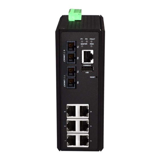
Figure 2.2: The Front Panel of PG5-0802-M-24 Series Top View Figure 2.3, below, shows the top panel of the PG5-0802-M-24 series switch that is equipped with one 6-pin removal terminal block connector for dual DC power inputs (12~55VDC). Figure 2.3: Top Panel View of PG5-0802-M-24 Series... - Page 10 (LAN Port 1-6) Not connected to a Powered Device Table 2.4: LED Indictors for PG5-0802-M-24 Series Caution: "P1/P2" is the abbreviation for "Power 1/Power 2", "L" is for "Link", and "A" is for "Activity", “GE” is for “Gigabit Ethernet Port”.
-
Page 11: Ethernet Ports
Ethernet Ports RJ-45 Ports (Auto MDI/MDIX) The RJ-45 ports are auto-sensing for 10Base-T, 100Base-TX or 1000Base-T devices connections. Auto MDI/MDIX means that the switch can connect to another switch or workstation without changing the straight-through or crossover cabling. See the figures as below for straight-through and crossover cabling schematics. -
Page 12: Cabling
Fiber Port The fiber port of SC/ST type connector can work in multi-mode or single-mode. When connecting the fiber port to another one, please follow the figure below to connect accordingly. Wrong connection will cause the port works abnormally. Figure 2.7: SC Connector Caution: This is a Class 1 Laser/LED product. -
Page 13: Wiring The Fault Alarm Contact
Step 2 Tighten the wire-clamp screws to prevent the wires from loosening, as shown below in Figure 2.9. Figure 2.9: Power Terminal Block Caution: Only use copper conductors, 100°C, tighten to 5 in-lbs. The wire gauge for the terminal block should range between 18~20 AWG. Wiring the Fault Alarm Contact The fault alarm contact is in the middle of the terminal block connector as the picture shows below in Figure 2.10. -
Page 14: Grounding Note
Grounding Note Grounding and wire routing help limit the effects of noise due to electromagnetic interference (EMI). Run the ground connection from the ground screw to the grounding surface prior to connecting devices. The grounding screw symbol is shown blow in Figure 2.11. Figure 2.11: Grounding screw Caution: Using a shielded cable achieves better electromagnetic compatibility. -
Page 15: Mounting Installation
Mounting Installation DIN-Rail Mounting The DIN-Rail is pre-installed on the industrial Ethernet switch from the factory. If the DIN-Rail is not on the industrial Ethernet switch, please see Figure 3.1 to learn how to install the DIN-Rail on the switch. Figure 3.1: The Rear Side of the Switch and DIN-Rail Bracket Follow the steps below to learn how to hang the industrial Ethernet switch. - Page 16 the DIN-Rail on to the track as shown below in Figure 3.2. Figure 3.2: Insert the Switch on the DIN-Rail Step 4 Lightly pull down the bracket on to the rail as shown below in Figure 3.3. Figure 3.3: Stable the Switch on DIN-Rail Step 5 Check if the bracket is mounted tightly on the rail.
-
Page 17: Wall Mounting
Wall Mounting Follow the steps below to mount the industrial Ethernet switch using the wall mounting bracket as shown below in Figure 3.4. Caution: “Wall” means industrial control panel wall. Step 1 Remove the DIN-Rail bracket from the industrial Ethernet switch by loosening the screws. -
Page 18: Hardware Installation
Hardware Installation Installation Steps This section will explain how to install PG5-0802-M-24 series. Caution: This device is intended for use indoor and at altitudes up to 2000 meters. Caution: The device is intended to be installed in an industrial control enclosure and panel... -
Page 19: Maintenance And Service
Maintenance and Service If the device requires servicing of any kind, the user is required to disconnect and remove it • from its mounting. The initial installation should be done in a way that makes this as convenient as possible. Voltage/Power lines should be properly insulated as well as other cables. -
Page 20: Trouble Shooting
If the power indicator LED does not turn on when the power cord is plugged in, the user may have a problem with the power cord. Check for loose power connections, power losses or surges at the power outlet. Please contact LEONTON for technical support service, if the problem still cannot be resolved. •...
Need help?
Do you have a question about the PG5-0802-M-24 Series and is the answer not in the manual?
Questions and answers