Table of Contents
Advertisement
Quick Links
Advertisement
Table of Contents

Related Manuals for Cole Parmer Electrothermal MC5


Summary of Contents for Cole Parmer Electrothermal MC5
- Page 1 Heating Controller MC5, MC5X1 Instruction Manual M7044 / Version 3.6...
-
Page 2: Table Of Contents
Please take your time to read this Instruction manual in order to understand the safe and correct use of your new Electrothermal product. It is recommended the responsible Body for the use of this equipment reads this instruction manual and ensures the user(s) are suitably trained in its operation. Contents Page Section 1... -
Page 3: Introduction
INTRODUCTION 1.1. The MC5 Controller has been designed to provide a comprehensive answer to control the heating of resistive loads such as the Electrothermal Electric Bunsen, Heating Mantles and Heating Tapes for bench top operation delivering up to a maximum of 800W. -
Page 4: Symbols And Using This Instruction Manual
SYMBOLS AND USING THIS INSTRUCTION MANUAL 2.1. Throughout this Instruction manual the following symbols are shown to identify conditions which pose a hazard to the user, or to identify actions that should be observed. These symbols are also shown on the product, or its packaging. When a symbol is shown next to a paragraph or statement it is recommended the user takes particular note of that instruction in order to prevent damage to the equipment or to YMBOLS AND USING THIS INSTRUCTION BOOK. -
Page 5: Safety Information
3. SAFETY INFORMATION. This product has been designed for safe operation when used as detailed in SAFETY INFORMATION accordance with the manufacturer’s instructions. 3. SAFETY INFORMATION. This product has been designed for safe operation when used as detailed in accordance NOTE: Failure to use this equipment in accordance with this instruction book may with the manufacturer’s instructions. - Page 6 applicable to your areas of operation. Check laboratory procedures Replace fuses only with the type as listed in section, Parts and Always follow good laboratory practice when using this Ensure the Mains Power Supply conforms to rating found on the whilst power is applied.
-
Page 7: Unpacking And Contents
4. UNPACKING AND CONTENTS. UNPACKING AND CONTENTS 4.1. Please check the contents of your carton against the diagram. 4.1. Please check the contents of your carton against the diagram. 4. UNPACKING AND CONTENTS. 4.1. Please check the contents of your carton against the diagram. (Mains plug and cord set may differ from illustration). -
Page 8: Installation
INSTALLATION 5. INSTALLATION. 5.1. Electrical safety and Installation 5.1. Electrical safety and Installation. 5.2. This equipment is designed for safe operation under the following conditions:- 5.2. This equipment is designed for safe operation under the following conditions:- • Indoor use. Indoor use. -
Page 9: Environmental Protection
6. ENVIRONMENTAL PROTECTION. 6. ENVIRONMENTAL PROTECTION. ENVIRONMENTAL PROTECTION 6. ENVIRONMENTAL PROTECTION. 6.1. Maximum consideration to environmental issues within the design and 6.1. Maximum consideration has to be given to environmental issues within the design and 6.1. Maximum consideration to environmental issues within the design and manufacturing process without compromising end product performance and value. -
Page 10: Equipment Operation
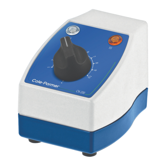
7.1. The MC5 controller has been designed for easy operation. The illustrations below show detailed layouts of this control unit. EQUIPMENT OPERATION 7. EQUIPMENT OPERATION. 7.1. The MC5 controller has been designed for easy operation. The illustrations below show 7.1. The MC5 controller has been designed for easy operation. The illustrations below show detailed layouts of this control unit. - Page 11 7.3. Connect to the mains electricity supply. Observe the white neon lamp is illuminated showing the presence of mains electricity. 7.3. Connect the other end to your MC controller. 7.4. Connect to the mains electricity supply. Observe the white neon lamp is illuminated showing 7.4.
-
Page 12: Technical Specification
TECHNICAL SPECIFICATION Mains supply voltage MC5 230V AC 50/60 Hz 8. TECHNICAL SPECIFICATION. Mains supply voltage MC5X1 115V AC 50/60 Hz 8.1. Specifications. Maximum coupled power 800 Watts consumption 230V Mains supply voltage 230V AC 50/60 Hz Mains supply voltage MC5X1 115V AC 50/60 Hz Maximum coupled power 460 Watts... -
Page 13: Maintenance
9. MAINTENANCE 9. MAINTENANCE 9.1. General Information. MAINTENANCE MAINTENANCE. 9.1. General Information. 9.1. General Information. 9.1. General information. Unplug the unit from the mains voltage supply and allow it to cool Unplug the unit from the mains voltage supply before undertaking any before undertaking any maintenance tasks. - Page 14 9.3. Replacing the Energy Regulator 9.3.1. Remove the energy regulator knob by pulling in a vertical direction away from the unit. 9.3.2. Remove and retain the regulator spindle locknut and shakeproof washer. 9.3.2. Remove and retain the regulator spindle locknut and shakeproof washer. 9.3.2.
- Page 15 Reassemble 9.3.5. Position new energy regulator and then fit and tighten the shake proof washer and the locknut. 9.3.6. Replace the energy regulator control knob ensuring the flat on surface on the energy 9.3.6. Replace the energy regulator control knob ensuring the flat on surface on the energy 9.3.6.
- Page 16 9.5. Replacing the Controller Output lead. 9.5. Replacing the Controller Output lead. 9.5. Replacing the Controller Output lead. 9.5.1. Turn the controller off and remove it from the mains supply. Disconnect it from any 9.5.1. Turn the controller off and remove it from the mains supply. Disconnect it from any 9.5.1.
- Page 17 9.5.11. Reconnect the mains and neutral wires from the cable to the PCB. (See wire 9.5.11. Reconnect the mains and neutral wires from the cable to the PCB. (See wire diagram). diagram). 9.3. Servicing. This product should be serviced by a Bibby Scientific Service Engineer or by an agent on behalf of Bibby Scientific l.
-
Page 18: Spares And Accessories
SPARES AND ACCESSORIES Order Number Description CRM5607 Neon clear (230V) CRM5619 Neon clear (115) CRM5608 Neon amber (230V) CRM5620 Neon amber (115V) HH179(S) Mains cord and moulded IEC plug and lead set cable (UK) 10A BS1362 HH180(S) Mains cord and moulded IEC plug and lead set cable (Europe) CRM6288 Mains cord and moulded IEC plug and lead... -
Page 19: Eu Declaration Of Conformity
This product meets applicable and so we cannot guarantee that interference will not harmonized standards for radio frequency occur in practice. Where there is a possibility that injury, interference and may be expected not to damage or loss might occur if equipment malfunctions interfere with, or be affected by, other equipment with due to radio frequency interference, or for general similar qualifications. - Page 20 Cole-Parmer Ltd. Beacon Road, Stone, Staffordshire, ST15 0SA, United Kingdom Tel: +44 (0)1785 812121 Email: cpinfo@coleparmer.com Web: www.electrothermal.com...
Need help?
Do you have a question about the Electrothermal MC5 and is the answer not in the manual?
Questions and answers