
Related Manuals for Cole Parmer Electrothermal MC810B


Summary of Contents for Cole Parmer Electrothermal MC810B
- Page 1 Digital Heating Controller MC810B, MC810BX1 Instruction Manual M6493 / Version 10.5...
-
Page 2: Table Of Contents
Please take your time to read this Instruction manual in order to understand the safe and correct use of your new Electrothermal product. It is recommended the responsible Body for the use of this equipment reads this instruction manual and ensures the user(s) are suitably trained in its operation. Contents Page Section 1... -
Page 3: Introduction
INTRODUCTION 1.1. The Electrothermal MC810B Digital Controller provides a convenient means of temperature control, using microprocessor techniques to give ease of operation and good accuracy. It can be used either in ON/OFF mode with the hysteresis loop controlling power switching or it can be used as a PID (Proportional, Integrated, Derivative) controller. -
Page 4: Symbols And Using This Instruction Manual
SYMBOLS AND USING THIS INSTRUCTION MANUAL 2.1. Throughout this Instruction manual the following symbols are shown to identify conditions which pose a hazard to the user, or to identify actions that should be observed. These symbols are also shown on the product, or its packaging. When a 2. -
Page 5: Safety Information
3. SAFETY INFORMATION. This product has been designed for safe operation when used as detailed in SAFETY INFORMATION accordance with the manufacturer’s instructions. 3. SAFETY INFORMATION. This product has been designed for safe operation when used as detailed in accordance NOTE: Failure to use this equipment in accordance with this instruction book may with the manufacturer’s instructions. - Page 6 implosion or the release of toxic or flammable gases) that might legislative health & safety procedures and all associated legislation 3.2. General Safe Operating Practice. Ensure the Mains Power Supply conforms to rating found on the Replace fuses only with the type as listed in section, Parts and arise have been suitably addressed before proceeding.
-
Page 7: Unpacking And Contents
UNPACKING AND CONTENTS 4. UNPACKING AND CONTENTS. Item Description Mains cord and moulded IEC plug and lead set. (May be different from illustration). MC810B MKII Digital Controller. Instruction Book Wall fixing Bkt x 1 and screws x 2 – per bag. Temperature Probe Serial Number Model Number... -
Page 8: Installation
INSTALLATION 5. INSTALLATION. 5. INSTALLATION. 5.1. Electrical safety and Installation 5.1. Electrical safety and Installation. 5.1. Electrical safety and Installation. 5.2. This equipment is designed for safe operation under the following conditions:- 5.2. This equipment is designed for safe operation under the following conditions:- 5.2. -
Page 9: Environmental Protection
6. ENVIRONMENTAL PROTECTION. 6. ENVIRONMENTAL PROTECTION. ENVIRONMENTAL PROTECTION 6. ENVIRONMENTAL PROTECTION. 6.1. Maximum consideration to environmental issues within the design and 6.1. Maximum consideration has to be given to environmental issues within the design and manufacturing process without compromising end product performance and value. 6.1. -
Page 10: Equipment Operation
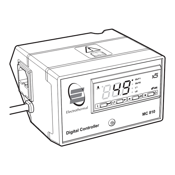
EQUIPMENT OPERATION 7. PRODUCT OPERATION. 7.1. The MC810B controller has been designed for easy operation. The illustrations below show detailed layouts of this control unit. 7.1. The MC810B controller has been designed for easy operation. The illustrations below show detailed layouts of this control unit. Instruction book label (refer to this book). - Page 11 7.2. Connection 7.2.1. Plug in the temperature probe to the 5 pin DIN socket. Place the temperature probe into the sample ensuring that at least 40mm of the probe tip is in contact with the 7.2. Connection. sample. Ensure the temperature probe is correctly plugged into the 5-pin DIN socket at 7.2.1.
- Page 12 7.3.3. Proportional, Integral and Derivative Control A proportional controller continuously adjusts the power, so the heat input to the 7.3.3. Proportional, Integral and De process is approximately in balance with the process heat requirements in order to 7.3.3. Proportional, Integral and Derivative Control. 7.3.3.
- Page 13 which power is adjusted is from 0% to 100%. This temperature range is A proportional controller continuously adjusts the power, so the heat input to which power is adjusted is from 0% to 100%. This temperature range is basic on / off control). A proportional controller continuously adjusts the power, so the heat input to called the ‘Proportional Band’.
- Page 14 and can help to reduce overs Hence, a three-mode P derivative actions, to allow the set point temperature to be the display or to scroll through the parameter menu. The MC810B controller has four front panel keys as described relatively smoothly with minimal overshoo 7.3.3.
- Page 15 door is opened or cooler fluid is introduced into a controlled ve Hence, a three-mode PID controller combines the proportional, integral and relatively smoothly with minimal overshoot. Hence, a three-mode PID controller combine the display or to scroll through the pa derivative function increases the controller gain during temper Hence, a three-mode PID controller combines the proportional, integral and derivative actions, to allow the set point temperature to be approached...
- Page 16 0..999s Integral action time. The steady-state error is cancelled by inserting an integral action. The integral action time, determines the speed with which the steady-state temperature is achieved, but a high speed (1IT low) may be the cause of the overshoot and instability in the response.
- Page 17 *ATM NON; Alarm threshold management. NON: all temperature alarms are inhibited (the following parameter will be SB). ABS; ABS: the value programmed in ALM and AHA represent the real alarm thresholds. REL: the value programmed in ALR and AHR are alarm differentials reerreed to 1SP and 1SP+1HY -50°...
-
Page 18: Technical Specification
TECHNICAL SPECIFICATION Mains supply voltage 110-120V~AC 50/60 Hz – (MC810BX1, MKII) 220-240V~AC 50/60 Hz – (MC810B, MKII) Maximum load 115V = Watts 1500 230V = Watts Controller power consumption 115V = 2W 8. TECHNICAL SPECIFICATIONS. 230V = 2W Mains supply voltage 110-120V~AC 50/60 Hz –... -
Page 19: Maintenance
9. MAINTENANCE 9.1. General Information. 9. MAINTENANCE 9.1. General Information. MAINTENANCE 9.1. General Information. Unplug the unit from the mains voltage supply before undertaking any 9.1. General Information. maintenance tasks. Unplug the unit from the mains voltage supply before undertaking any Unplug the unit from the mains voltage supply before undertaking any maintenance tasks. - Page 20 The temperature difference between the stabilised tempera The temperature difference between the stabilised temperature and the set term of the PID controller. This is achieved using the integrative actio term of the PID controller. This is achieved using the derivative function increases the controller gain during temperatur differing process conditions (z and integrative action reset.
-
Page 21: Spares And Accessories
SPARES AND ACCESSORIES Order Number Description HH179(S) Mains cord and moulded IEC plug and lead set cable (UK) 10A BS1362 HH180(S) Mains cord and moulded IEC plug and lead set cable (Europe) Mains cord and moulded IEC plug and lead CRM6288 set cable (USA) Mains cord and moulded IEC plug and lead... -
Page 22: Notes
NOTES... -
Page 23: Ec Declaration Of Conformity
This product meets applicable and so we cannot guarantee that interference will not harmonized standards for radio frequency occur in practice. Where there is a possibility that injury, interference and may be expected not to damage or loss might occur if equipment malfunctions interfere with, or be affected by, other equipment with due to radio frequency interference, or for general similar qualifications. - Page 24 Cole-Parmer Ltd. Beacon Road, Stone, Staffordshire, ST15 0SA, United Kingdom Tel: +44 (0)1785 812121 Email: cpinfo@coleparmer.com Web: www.electrothermal.com...
Need help?
Do you have a question about the Electrothermal MC810B and is the answer not in the manual?
Questions and answers