
Subscribe to Our Youtube Channel
Related Manuals for Asus PB50 BR072MD


Summary of Contents for Asus PB50 BR072MD
- Page 1 Questo manuale d’istruzione è fornito da trovaprezzi.it. Scopri tutte le offerte per Asus PB50 BR072MD o cerca il tuo prodotto tra le migliori offerte di PC Desktop e Workstation Mini PC PB50 Series User Manual...
- Page 2 Copyright © 2019 ASUSTeK COMPUTER INC. All Rights Reserved. LIMITATION OF LIABILITY Circumstances may arise where because of a default on ASUS’ part or other liability, you are entitled to recover damages from ASUS. In each such instance, regardless of the basis on which you are entitled to claim damages from ASUS, ASUS is liable for no more than damages for bodily injury (including death) and damage to real property and tangible personal property;...
-
Page 3: Table Of Contents
Contents About this manual .........................5 Conventions used in this manual ..................6 Typography ..........................6 Package contents ........................7 Getting to know your Mini PC Features .............................10 Front view ..........................10 Left view ..........................12 Rear view ..........................13 Using your Mini PC Getting started ........................18 Mounting your device on the stand ................18 Connect the AC power adapter to your Mini PC............19 Connect a display panel to your device ................21... - Page 4 Appendix Safety information .........................40 Setting up your system .......................40 Care during use ........................40 Regulatory notices ........................42 PB50 Series...
-
Page 5: About This Manual
About this manual This manual provides information about the hardware and software features of your Mini PC, organized through the following chapters: Chapter 1: Getting to know your Mini PC This chapter details the hardware components of your Mini PC. Chapter 2: Using your Mini PC This chapter provides you with information on using your Mini PC. -
Page 6: Conventions Used In This Manual
Conventions used in this manual To highlight key information in this manual, some text are presented as follows: IMPORTANT! This message contains vital information that must be followed to complete a task. NOTE: This message contains additional information and tips that can help complete tasks. -
Page 7: Package Contents
Package contents Your Mini PC package contains the following items: Mini PC AC power adapter* Power cord* Technical documents PB50 Series... - Page 8 For details on these accessories, refer to their respective user manuals. • T he device illustration is for reference only. Actual product specifications may vary with models. • I f the device or its components fail or malfunction during normal and proper use within the warranty period, bring the warranty card to the ASUS Service Center for replacement of the defective components. PB50 Series...
-
Page 9: Getting To Know Your Mini Pc
Getting to know your Mini... -
Page 10: Features
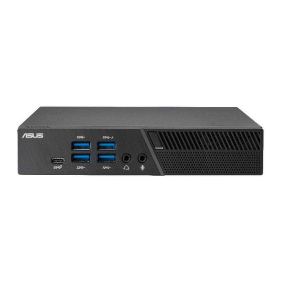
Features Front view USB 3.1 Gen 1 port The USB 3.1 Gen 1 (Universal Serial Bus) port provides a transfer rate up to 5 Gbit/s. These ports also support the Battery Charging 1.2 technology that allows you to charge your USB devices. NOTE: This port provides a maximum of 5V / 1.5A output. - Page 11 Air vents (intake vent) The air vents allow cooler air to enter your Mini PC chassis. IMPORTANT: For an optimum heat dissipation and air ventilation, ensure that the air vents are free from obstructions. USB 3.1 Gen 2 Type-C™ port This USB Type-C™...
-
Page 12: Left View
Left view Graphics module port This port allows you to connect the Graphics module with your Mini PC. If the port cover is attached, remove the cover before installing the Graphics module to your Mini NOTE: The availability of the Graphic module may vary between models and territories. -
Page 13: Rear View
Rear view Wireless antenna jack The jack is used to connect the supplied wireless antenna to enhance wireless signal reception. Air vents (exhaust vent) The air vents allow your Mini PC chassis to expel hot air out. IMPORTANT! For optimum heat dissipation and air ventilation, ensure that the air vents are free from obstructions. - Page 14 Configurable port This port varies between models and consists of the following port options: VGA port This port allows you to connect your Mini PC to an external display. Serial (COM) connector The 9-pin serial (COM) connector allows you to connect devices that have serial ports such as mouse, modem, or printers.
- Page 15 DisplayPort This port allows you to connect your Mini PC to an external display. HDMI port The HDMI (High Definition Multimedia Interface) port supports a Full-HD device such as an LCD TV or monitor to allow viewing on a larger external display. USB 3.1 Gen 2 port The USB 3.1 Gen 2 (Universal Serial Bus) port provides a transfer rate up to 10 Gbit/s.
- Page 16 PB50 Series...
-
Page 17: Using Your Mini Pc
Using your Mini PC... -
Page 18: Getting Started
Getting started Mounting your device on the stand To mount your Mini PC on the stand: Locate the mounting holes at the bottom of your Mini PC. Align the stand’s mounting hole with the mounting hole on your Mini PC, then secure it in place with the stand screws. stand screws PB50 Series... -
Page 19: Connect The Ac Power Adapter To Your Mini Pc
Connect the AC power adapter to your Mini PC To connect the AC power adapter to your Mini PC: Connect the power cord to the AC power adapter. Connect the DC power connector into your Mini PC’s power (DC) input. Plug the AC power adapter into a 100V~240V power source. - Page 20 NOTE: The power adapter may vary between models and territories, please refer to the following for more information on the different adapters: 65W Power adapter • Input voltage: 100-240 Vac • Input frequency: 50-60 Hz • Rating output current: 3.42 A (65 W) • Rating output voltage: 19 V 90W Power adapter • Input voltage: 100-240 Vac • Input frequency: 50-60 Hz • Rating output current: 4.74 A (90W) • Rating output voltage: 19 V PB50 Series...
-
Page 21: Connect A Display Panel To Your Device
Connect a display panel to your device You can connect a display panel or projector to your device that has the following connectors: • VGA connector • DisplayPort • HDMI connector NOTE: These ports may vary per model. To connect a display panel to your Mini PC: Connect one end of a VGA, DisplayPort, or HDMI cable to an external display, and the other end of the cable to your Mini PC’s VGA port, DisplayPort, or an HDMI port. - Page 22 Connect display via DisplayPort Connect display via HDMI port PB50 Series...
-
Page 23: Connect The Usb Cable From Keyboard Or Mouse
Connect the USB cable from keyboard or mouse You can connect generally any USB keyboard and mouse to your Mini PC. You can also connect a USB dongle for a wireless keyboard and mouse set. To connect a keyboard and mouse to your Mini PC: Connect the USB cable from your keyboard and mouse to any of the USB ports of your Mini PC. -
Page 24: Turn On Your Mini Pc
Turn on your Mini PC Press the power button to turn on your Mini PC. PB50 Series... -
Page 25: Turning Your Mini Pc Off
Turning your Mini PC off If your Mini PC is unresponsive, press and hold the power button for at least four (4) seconds until your Mini PC turns off. Putting your Mini PC to sleep To put your Mini PC on Sleep mode, press the Power button once. Entering the BIOS Setup BIOS (Basic Input and Output System) stores system hardware settings that are needed for system startup in the Mini PC. -
Page 26: Load Default Bios Settings
Load default BIOS settings To load the default values for each of the parameters in your BIOS: • Enter the BIOS by pressing <F2> or <DEL> on the POST screen. NOTE: POST (Power-On Self Test) is a series of software controlled diagnostic tests that run when you turn on your Mini PC. •... -
Page 27: Upgrading Your Mini Pc
Upgrading your Mini PC... -
Page 28: Removing The Top Cover
IMPORTANT! Ensure that your hands are dry before proceeding with the rest of the installation process. Before installing any of the features in this guide, use a grounded wrist strap or touch a safely grounded object or metal object to avoid damaging them due to static electricity. -
Page 29: Replacing The Top Cover
Replacing the top cover Replace the top cover and push it towards the rear (A), then secure it with the screw removed previously (B). PB50 Series... -
Page 30: Installing 2.5" Hdd Or Ssd
Installing 2.5” HDD or SSD Remove the four (4) screws, then lift the storage bay to remove it from the chassis. Insert your HDD or SSD into the storage bay, then secure it with four (4) screws. Connect the SATA cable to the HDD or SSD. PB50 Series... - Page 31 Lift the flap on the SATA connector (A), connect the SATA cable to the SATA connector, then push the flap down to secure the cable (B). Replace the storage bay and secure it with the four (4) screws removed previously. PB50 Series...
-
Page 32: Installing The M.2 Ssd
Installing the M.2 SSD (optional) Remove the storage bay if a storage bay is installed. Follow step 2 under the Installing 2.5” HDD or SSD section to remove the storage bay. To install 2242 M.2 SSD Align and insert the 2242 M.2 SSD into its slot inside the Mini PC, then gently push down the M.2 SSD on top of the screw hole and fasten it using one of the bundled 3mm round screws. - Page 33 To install 2280 M.2 SSD Remove the stand screw and install it into the 2280 M.2 screw hole. Align and insert the 2280 M.2 SSD into its slot inside the Mini PC, then gently push down the M.2 SSD on top of the screw hole and fasten it using one of the bundled 3mm round screws.
-
Page 34: Installing Top Memory Module
Installing top memory module IMPORTANT! • R efer to http://www.asus.com for the list of compatible DIMMs. You can only install DDR4 SO-DIMMs to the Mini PC’s DIMM slot. • O nly ASUS-authorized technicians should remove and install motherboard and mechanical parts inside your Mini PC. Please refer to the terms and conditions in the warranty card. - Page 35 Align and insert the memory module into the slot (A) and press it down (B) until it is securely seated in place. PB50 Series...
-
Page 36: Installing The Wireless Card
Installing the wireless card NOTE: Your Mini PC includes a M.2 slot for 2230 wireless and Bluetooth modules. Refer to http://www.asus.com for the list of compatible wireless and Bluetooth modules. Follow steps 1 and 2 under the Installing top memory module section to lift the fan before installing the wireless card. -
Page 37: Installing An External Button
Installing an external button Remove the metal cover of the punch-out port. CAUTION! Take extra care when removing the metal cover. Use tools such as a screw driver to bend and remove the metal cover to avoid physical injury. Insert the external button connector through the punch-out port and connect it to one of the following 2-pin headers: Header name Description... - Page 38 PB50 Series...
-
Page 39: Appendix
Appendix... -
Page 40: Safety Information
Safety information Your Mini PC is designed and tested to meet the latest standards of safety for information technology equipment. However, to ensure your safety, it is important that you read the following safety instructions. Setting up your system • Read and follow all instructions in the documentation before you operate your system. • Do not use this product near water or a heated source. • Set up the system on a stable surface. • Openings on the chassis are for ventilation. Do not block or cover these openings. - Page 41 • If you encounter the following technical problems with the product, unplug the power cord and contact a qualified service technician or your retailer. – The power cord or plug is damaged. – Liquid has been spilled into the system. – The system does not function properly even if you follow the operating instructions. – The system was dropped or the cabinet is damaged. – The system performance changes.
-
Page 42: Regulatory Notices
ASUS REACH website at http://csr.asus.com/ english/REACH.htm ASUS Recycling/Takeback Services ASUS recycling and takeback programs come from our commitment to the highest standards for protecting our environment. We believe in providing solutions for you to be able to responsibly recycle our products, batteries, other components, as well as the packaging materials. - Page 43 Federal Communications Commission Statement This device complies with Part 15 of the FCC Rules. Operation is subject to the following two conditions: • This device may not cause harmful interference, and • This device must accept any interference received including interference that may cause undesired operation. This equipment has been tested and found to comply with the limits for a Class B digital device, pursuant to Part 15 of the FCC Rules. These limits are designed to provide reasonable protection against harmful interference in a residential installation.
- Page 44 ISED Radiation Exposure Statement for Canada This equipment complies with ISED radiation exposure limits set forth for an uncontrolled environment. To maintain compliance with ISED RF exposure compliance requirements, please avoid direct contact to the transmitting antenna during transmitting. End users must follow the specific operating instructions for satisfying RF exposure compliance. Operation is subject to the following two conditions: •...
- Page 45 Wireless Operation Channel for Different Domains N. America 2.412-2.462 GHz Ch01 through CH11 Japan 2.412-2.484 GHz Ch01 through Ch14 Europe ETSI 2.412-2.472 GHz Ch01 through Ch13 Regional notice for California WARNING Cancer and Reproductive Harm - www.P65Warnings.ca.gov PB50 Series...
- Page 46 Agency and the U.S. Department of Energy helping us all save money and protect the environment through energy efficient products and practices. All ASUS products with the ENERGY STAR logo comply with the ENERGY STAR standard, and the power management feature is enabled by default.
Need help?
Do you have a question about the PB50 BR072MD and is the answer not in the manual?
Questions and answers