Table of Contents

Subscribe to Our Youtube Channel
Related Manuals for Edgewater Networks EdgeConnect 2402PoE


Summary of Contents for Edgewater Networks EdgeConnect 2402PoE
- Page 1 EdgeConnect 2402PoE LF Managed Ethernet Switch Installation Guide Version 1.0 U.S. Headquarters: 2895 Northwestern Parkway Santa Clara, CA 95051 Phone: +1 (408) 351-7200 Fax: +1 (408) 727-6430 www.edgewaternetworks.com EWN005-05-D001...
- Page 2 No part of this document may be reproduced in any form by any means without prior written authorization of Edgewater Networks, Inc. Documentation is provided “as is” without warranty of any kind, either express or implied, including any kind of implied or express warranty of non- infringement of the implied warranties of merchantability or fitness for a particular purpose.
- Page 3 Compliances and Safety Warnings FCC - Class A This equipment has been tested and found to comply with the limits for a Class A digital device, pursuant to part 15 of the FCC Rules. These limits are designed to provide reasonable protection against harmful interference when the equipment is operated in a commercial environment.
- Page 4 CE Mark Declaration of Conformance for EMI and Safety (EEC) This information technology equipment complies with the requirements of the Council Directive 89/336/EEC on the Approximation of the laws of the Member States relating to Electromagnetic Compatibility and 73/23/EEC for electrical equipment used within certain voltage limits and the Amendment Directive 93/68/EEC.
- Page 5 Safety Compliance Warning: Fiber Optic Port Safety When using a fiber optic port, never look at the transmit laser while it is powered on. Also, never look directly at the fiber TX port and fiber cable ends when they are powered on. Power Cord Safety Please read the following safety information carefully before installing...
- Page 6 Power Cord Set Switzerland The supply plug must comply with SEV/ASE 1011. U.K. The supply plug must comply with BS1363 (3-pin 13 A) and be fitted with a 5 A fuse which complies with BS1362. The mains cord must be <HAR> or <BASEC> marked and be of type HO3VVF3GO.75 (minimum).
- Page 7 Environmental Statement The manufacturer of this product endeavours to sustain an environmentally-friendly policy throughout the entire production process. This is achieved though the following means: • Adherence to national legislation and regulations on environmental production standards. • Conservation of operational resources. •...
-
Page 8: Table Of Contents
ABLE OF ONTENTS About the !"#$%&''$() ......1-1 Overview ..........1-1 Switch Architecture . - Page 9 ABLE OF ONTENTS Installing an Optional SFP Transceiver ......3-7 Connecting to a Power Source ....... . 3-8 Connecting to the Console Port .
- Page 10 ABLE OF ONTENTS Management Features ........C-3 Standards .
- Page 11 ABLES Table 1-1 Port Status LEDs ....... . . 1-4 Table 1-2 System Status LED .
- Page 12 IGURES Figure 1-1 Front and Rear Panels ......1-1 Figure 1-2 Port Status LEDs ....... 1-4 Figure 1-3 System Status LED .
-
Page 14: Overview
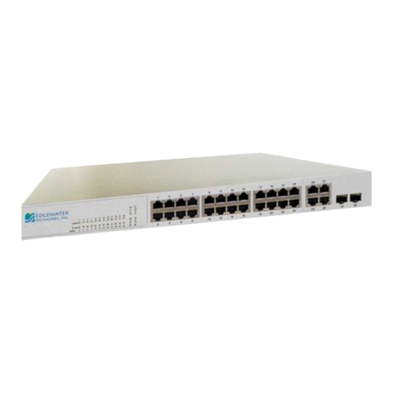
Chapter 1: Introduction Overview The 2402PoE LF switch features 24 10/100BASE-T ports, two 10/100/1000BASE-T ports, and two Gigabit combination ports that are comprised of an RJ-45 port and an SFP transceiver slot. There is also an SNMP-based management agent embedded on the main board. This agent supports both in-band and out-of-band access for managing the switch. -
Page 15: Switch Architecture
Switch Architecture The switch employs a wire-speed, non-blocking switching fabric. This permits simultaneous wire-speed transport of multiple packets at low latency on all ports. The switch also features full-duplex capability on all ports, which effectively doubles the bandwidth of each connection. he switch uses store-and-forward switching to ensure maximum data integrity. -
Page 16: Network Management Options
ESCRIPTION OF ARDWARE Network Management Options The switch contains a comprehensive array of LEDs for “at-a-glance” monitoring of network and port status. It also includes a management agent that allows you to configure or monitor the switch using its embedded management software, or via SNMP applications. -
Page 17: Port And System Status Leds
Port and System Status LEDs The LEDs, which are located on the front panel for easy viewing, are shown below and described in the following table. Combination Gigabit Port Status LEDs Port Status LEDs 25 27 Link/Act 26 28 System Figure 1-2 Port Status LEDs Table 1-1 Port Status LEDs... -
Page 18: Table 1-2 System Status Led
ESCRIPTION OF ARDWARE System Status LED 25 27 Link/Act 26 28 System Figure 1-3 System Status LED Table 1-2 System Status LED Condition Status System On Green Internal power is operating normally. On Amber Internal power supply has failed. Power off or failure. -
Page 19: Power Supply Sockets
Power Supply Sockets There is one standard power socket on the rear panel of the switch for the AC power cord. Power Socket Console Port RATING 100~240V- 3A 50~60HZ Figure 1-4 Power Supply Sockets Features and Benefits Connectivity • 24 10/100BASE-T ports plus 2 Gigabit combination ports (RJ-45/SFP) and 2 Gigabit 1000BASE-T ports. -
Page 20: Expandability
EATURES AND ENEFITS Expandability • 2 Small Form Factor Pluggable (SFP) transceiver slots (shared with 1000BASE-T ports) • Supports 1000BASE-SX and 1000BASE-LX, 1000BASE-ZX and other SFP-compatible transceivers. Performance • Transparent bridging • Switching table with a total of 8K MAC address entries •... -
Page 21: Introduction To Switching
HAPTER ETWORK LANNING Introduction to Switching A network switch allows simultaneous transmission of multiple packets via non-crossbar switching. This means that it can partition a network more efficiently than bridges or routers. The switch has, therefore, been recognized as one of the most important building blocks for today’s networking technology. -
Page 22: Application Examples
ETWORK LANNING Application Examples The !"#$%&''$()*+,-+.&! /0*is not only designed to segment your network, but also to provide a wide range of options in setting up network connections. Some typical applications are described in the following pages. Supplying PoE The switch is an excellent choice for supplying power to connected PoE devices such as web cameras, IP telephones or access points. -
Page 23: Collapsed Backbone
PPLICATION XAMPLES Collapsed Backbone The !"#$%&''$()*+,-+.&!*/0 is an excellent choice for mixed Ethernet, Fast Ethernet, and Gigabit Ethernet installations where significant growth is expected in the near future. In a basic stand-alone configuration, it can provide direct full-duplex connections to workstations or servers. When the time comes for further expansion, just connect to another hub or switch using one of the Fast Ethernet ports built into the front panel or a Gigabit Ethernet port on a plug-in SFP transceiver. -
Page 24: Network Aggregation Plan
ETWORK LANNING Network Aggregation Plan With 24 parallel bridging ports (i.e., 24 distinct collision domains), the switch can collapse a complex network down into a single efficient bridged node, increasing overall bandwidth and throughput. In the figure below, the 10/100BASE-TX ports on the switch are providing 100 Mbps connectivity through layer 2 switches. -
Page 25: Remote Connection With Fiber Cable
PPLICATION XAMPLES Remote Connection with Fiber Cable Fiber optic technology allows for longer cabling than any other media type. A 1000BASE-SX (MMF) link can connect to a site up to 550 meters away, a 1000BASE-LX (SMF) link up to 5 km, and a 1000BASE-ZX link up to 100 km. -
Page 26: Making Vlan Connections
ETWORK LANNING Making VLAN Connections The switch supports VLANs which can be used to organize any group of network nodes into separate broadcast domains. VLANs confine broadcast traffic to the originating group, and can eliminate broadcast storms in large networks. This provides a more secure and cleaner network environment. VLANs can be based on untagged port groups, or traffic can be explicitly tagged to identify the VLAN group to which it belongs. -
Page 27: Application Notes
PPLICATION OTES Application Notes 1. Full-duplex operation only applies to point-to-point access (such as when a switch is attached to a workstation, server or another switch). When the switch is connected to a hub, both devices must operate in half-duplex mode. 2. - Page 28 ETWORK LANNING...
-
Page 29: Installing The Switch
HAPTER NSTALLING THE WITCH Selecting a Site 2402PoE LF u on a flat surface. Be sure to follow the guidelines below when choosing a location. • The site should: - be at the center of all the devices you want to link and near a power outlet. -
Page 30: Ethernet Cabling
NSTALLING THE WITCH Ethernet Cabling To ensure proper operation when installing the switch into a network, make sure that the current cables are suitable for 10BASE-T, 100BASE-TX or 1000BASE-T operation. Check the following criteria against the current installation of your network: •... -
Page 31: Equipment Checklist
QUIPMENT HECKLIST Equipment Checklist After unpacking the switch, check the contents to be sure you have received all the components. Then, before beginning the installation, be sure you have all other necessary installation equipment. Package Contents •**!"#$%&''$()*+,-+.&!*/0 • Four adhesive foot pads •... -
Page 32: Mounting
NSTALLING THE WITCH Mounting The switch unit can be mounted in a standard 19-inch equipment rack or on a desktop or shelf. Mounting instructions for each type of site follow. Rack Mounting Before rack mounting the switch, pay particular attention to the following factors: •... -
Page 33: Figure 3-2 Attaching The Brackets
OUNTING To rack-mount devices: 1. Attach the brackets to the device using the screws provided in the Bracket Mounting Kit. Figure 3-2 Attaching the Brackets 2. Mount the device in the rack, using four rack-mounting screws (not provided). Figure 3-3 Installing the Switch in a Rack... -
Page 34: Desktop Or Shelf Mounting
NSTALLING THE WITCH 3. If installing a single switch only, turn to “Connecting to a Power Source” at the end of this chapter. 4. If installing multiple switches, mount them in the rack, one below the other, in any order. Desktop or Shelf Mounting 1. -
Page 35: Installing An Optional Sfp Transceiver
SFP T NSTALLING AN PTIONAL RANSCEIVER Installing an Optional SFP Transceiver Figure 3-5 Inserting an SFP Transceiver into a Slot The SFP slots support the following optional SFP transceivers: • 1000BASE-SX • 1000BASE-LX • 1000BASE-ZX To install an SFP transceiver, do the following: 1. -
Page 36: Connecting To A Power Source
NSTALLING THE WITCH Connecting to a Power Source To connect a device to a power source: 1. Insert the power cable plug directly into the socket located at the back of the device. RATING 100~240V- 3A 50~60HZ Figure 3-6 Power Socket 2. -
Page 37: Connecting To The Console Port
ONNECTING TO THE ONSOLE Connecting to the Console Port The DB-9 serial port on the switch’s front panel is used to connect to the switch for out-of-band console configuration. The on-board configuration program can be accessed from a terminal or a PC running a terminal emulation program. - Page 38 NSTALLING THE WITCH 3-10...
-
Page 39: Making Network Connections
HAPTER AKING ETWORK ONNECTIONS Connecting Network Devices The !"#$%&''$()*+,-+.&!*/0 is designed to interconnect multiple segments (or collision domains). It can be connected to network cards in PCs and servers, as well as to hubs, switches or routers. It may also be connected to devices using optional SFP tranceivers. -
Page 40: Power-Over-Ethernet Connections
AKING ETWORK ONNECTIONS Power-over-Ethernet Connections The PoE switch automatically detects an 802.3af-compliant device by its authenticated PoE signature and senses its required load before turning on DC power to the port. This detection mechanism prevents damage to other network equipment that is not 802.3af compliant. Note: Power-over-Ethernet connections work with all existing Category 3, 4, 5, 5e or 6 network cabling, including patch cables and patch-panels, outlets, and other connecting hardware, without... -
Page 41: Cabling Guidelines
WISTED EVICES Cabling Guidelines The RJ-45 ports on the switch supports automatic MDI/MDI-X pinout configuration, so you can use standard straight-through twisted-pair cables to connect to any other network device (PCs, servers, switches, routers, or hubs). See Appendix B for further information on cabling. Caution: Do not plug a phone jack connector into an RJ-45 port. -
Page 42: Network Wiring Connections
AKING ETWORK ONNECTIONS Make sure each twisted pair cable does not exceed 100 meters (328 ft) in length. 3. As each connection is made, the Link LED (on the switch) corresponding to each port will light to indicate that the connection is valid. -
Page 43: Fiber Optic Sfp Devices
SFP D IBER PTIC EVICES Equipment Rack Switch (side view) 25 27 Link/Act 26 28 System Punch-Down Block Patch Panel Wall Figure 4-2 Network Wiring Connections Fiber Optic SFP Devices An optional Gigabit SFP transceiver (1000BASE-SX, 1000BASE-LX, or 1000BASE-ZX) can be used for a backbone connection between switches, or for connecting to a high-speed server. - Page 44 AKING ETWORK ONNECTIONS Warning: When selecting a fiber SFP device, considering safety, please make sure that it can function at a temperature that is not less than the recommended maximum operational temperature of the product. You must also use an approved Laser Class 1 SFP transceiver.
-
Page 45: Figure 4-3 Making Fiber Port Connections
SFP D IBER PTIC EVICES Figure 4-3 Making Fiber Port Connections 4. As a connection is made, check the Link LED on the switch corresponding to the port to be sure that the connection is valid. The 1000BASE-SX, 1000BASE-LX and 1000BASE-ZX fiber optic ports operate at 1 Gbps full duplex, with auto-negotiation of flow control. -
Page 46: Connectivity Rules
AKING ETWORK ONNECTIONS Connectivity Rules When adding hubs (repeaters) to your network, please follow the connectivity rules listed in the manuals for these products. However, note that because switches break up the path for connected devices into separate collision domains, you should not include the switch or connected cabling in your calculations for cascade length involving other devices. -
Page 47: 1000 Mbps Gigabit Ethernet Collision Domain
ONNECTIVITY ULES 1000 Mbps Gigabit Ethernet Collision Domain Table 4-1 Maximum 1000BASE-T Gigabit Ethernet Cable Length Cable Type Maximum Cable Connector Length Category 5, 5e, 6 100-ohm UTP or 100 m (328 ft) RJ-45 Table 4-2 Maximum 1000BASE-SX Gigabit Ethernet Cable Length Fiber Size Fiber Maximum Cable... -
Page 48: 100 Mbps Fast Ethernet Collision Domain
AKING ETWORK ONNECTIONS 100 Mbps Fast Ethernet Collision Domain Table 4-5 Maximum Fast Ethernet Cable Length Type Cable Type Max. Cable Connector Length 100BASE-TX Category 5 or better 100-ohm UTP 100 m (328 ft) RJ-45 or STP 10 Mbps Ethernet Collision Domain Table 4-6 Maximum Ethernet Cable Length Type Cable Type... -
Page 49: Cable Labeling And Connection Records
ABLE ABELING AND ONNECTION ECORDS Cable Labeling and Connection Records When planning a network installation, it is essential to label the opposing ends of cables and to record where each cable is connected. Doing so will enable you to easily locate inter-connected devices, isolate faults and change your topology without need for unnecessary time consumption. - Page 50 AKING ETWORK ONNECTIONS 4-12...
-
Page 51: Troubleshooting
PPENDIX ROUBLESHOOTING Diagnosing Switch Indicators Table A-1 Troubleshooting Chart Symptom Action Power LED is Off • Power supply is disconnected. • Check connections between the switch, the power cord, and the wall outlet. • Contact your dealer for assistance. Power LED is •... -
Page 52: Power And Cooling Problems
ROUBLESHOOTING Power and Cooling Problems If the power indicator does not turn on when the power cord is plugged in, you may have a problem with the power outlet, power cord, or internal power supply. However, if the unit powers off after running for a while, check for loose power connections, power losses or surges at the power outlet, and verify that the fans on the unit are unobstructed and running prior to shutdown. -
Page 53: Cables
PPENDIX ABLES Twisted-Pair Cable and Pin Assignments For 10/100BASE-TX connections, a twisted-pair cable must have two pairs of wires. For 1000BASE-T connections the twisted-pair cable must have four pairs of wires. Each wire pair is identified by two different colors. For example, one wire might be green and the other, green with white stripes. -
Page 54: Table B-1 10/100Base-Tx Mdi-X And Mdi Port Pinouts
ABLES 10/100BASE-TX Pin Assignments Use unshielded twisted-pair (UTP) or shielded twisted-pair (STP) cable for RJ-45 connections: 100-ohm Category 3 or better cable for 10 Mbps connections, or 100-ohm Category 5 or better cable for 100 Mbps connections. Also be sure that the length of any twisted-pair connection does not exceed 100 meters (328 feet). -
Page 55: Twisted-Pair Cable And Pin Assignments
WISTED ABLE AND SSIGNMENTS Straight-Through Wiring If the twisted-pair cable is to join two ports and only one of the ports has an internal crossover (MDI-X), the two pairs of wires must be straight-through. (When auto-negotiation is enabled for any RJ-45 port on this switch, you can use either straight-through or crossover cable to connect to any device type.) You must connect all four wire pairs as shown in the following diagram to... -
Page 56: Crossover Wiring
ABLES Crossover Wiring If the twisted-pair cable is to join two ports and either both ports are labeled with an “X” (MDI-X) or neither port is labeled with an “X” (MDI), a crossover must be implemented in the wiring. (When auto-negotiation is enabled for any RJ-45 port on this switch, you can use either straight-through or crossover cable to connect to any device type.) You must connect all four wire pairs as shown in the following diagram to... -
Page 57: 1000Base-T Pin Assignments
WISTED ABLE AND SSIGNMENTS 1000BASE-T Pin Assignments All 1000BASE-T ports support automatic MDI/MDI-X operation, so you can use straight-through cables for all network connections to PCs or servers, or to other switches or hubs. The table below shows the 1000BASE-T MDI and MDI-X port pinouts. These ports require that all four pairs of wires be connected. - Page 58 ABLES ANSI/TIA/EIA-TSB-95 Bulletin, “The Additional Transmission Performance Guidelines for 100 Ohm 4-Pair Category 5 Cabling.” Note that when testing your cable installation, be sure to include all patch cables between switches and end devices. Adjusting Existing Category 5 Cabling to Run 1000BASE-T If your existing Category 5 installation does not meet one of the test parameters for 1000BASE-T, there are basically three measures that can be applied to try and correct the problem:...
-
Page 59: Specifications
PPENDIX PECIFICATIONS Physical Characteristics Ports 24 10/100BASE-TX, with auto-negotiation 2 10/100/1000BASE-T Ports 2 Combination Gigabit Ports (RJ-45/SFP) Network Interface Ports 1-24: RJ-45 connector, auto MDI/X 10BASE-T: RJ-45 (100-ohm, UTP cable; Category 3 or better) 100BASE-TX: RJ-45 (100-ohm, UTP cable; Category 5 or better) Ports 25-28: RJ-45 connector, auto MDI/X 1000BASE-T: RJ-45 (100-ohm, UTP cable;... -
Page 60: Switch Features
PECIFICATIONS Size 4.3 x 44 x 17.1 cm (1.7 x 17.3 x 6.7 in.) Temperature Operating: 0 to 45 °C (32 to 113 °F) Storage: -40 to 70 °C (-40 to 158 °F) Humidity Operating: 10% to 90% (non-condensing) Power Supply Internal, auto-ranging transformer: 100 to 240 V, 50-60 Hz, 3 A Power Consumption 225 Watts maximum... - Page 61 ANAGEMENT EATURES Management Features In-Band Management Telnet, HTTP or SNMP manager Out-of-Band Management RS-232 DB-9 console port Software Loading TFTP in-band, or XModem out-of-band Standards IEEE 802.3 Ethernet IEEE 802.3u Fast Ethernet IEEE 802.3z and 802.3ab Gigabit Ethernet IEEE 802.1D (Bridging) IEEE 802.3x full-duplex flow control IEEE 802.1Q (Virtual LAN) ISO/IEC 8802-3...
- Page 62 PECIFICATIONS Safety UL / CUL (UL 60950-1, CSA 22.2 NO60950-1) TUV/GS (EN60950-1) CB (IEC60950-1)
- Page 63 LOSSARY 10BASE-T IEEE 802.3 specification for 10 Mbps Ethernet over two pairs of Category 3, 4, or 5 UTP cable. 100BASE-TX IEEE 802.3u specification for 100 Mbps Ethernet over two pairs of Category 5 UTP cable. 1000BASE-LX Specification for long-haul Gigabit Ethernet over two strands of 50/125, 62.5/125 or 9/125 micron core fiber cable.
- Page 64 Bandwidth The difference between the highest and lowest frequencies available for network signals. Also synonymous with wire speed, the actual speed of the data transmission along the cable. Collision A condition in which packets transmitted over the cable interfere with each other.
- Page 65 Gigabit Ethernet A 1000 Mbps network communication system based on Ethernet and the CSMA/CD access method. Full Duplex Transmission method that allows two network devices to transmit and receive concurrently, effectively doubling the bandwidth of that link. IEEE Institute of Electrical and Electronic Engineers. IEEE 802.3 Defines carrier sense multiple access with collision detection (CSMA/CD) access method and physical layer specifications.
- Page 66 1000BASE Gigabit Ethernet. LAN Segment Separate LAN or collision domain. Light emitting diode used for monitoring a device or network condition. Local Area Network (LAN) A group of interconnected computer and support devices. Media Access Control (MAC) A portion of the networking protocol that governs access to the transmission medium, facilitating the exchange of data between network nodes.
- Page 67 Ports that are on separate collision domains or LAN segments. Telecommunications Industry Association Transmission Control Protocol/Internet Protocol (TCP/IP) Protocol suite that includes TCP as the primary transport protocol, and IP as the network layer protocol. Unshielded twisted-pair cable. Virtual LAN (VLAN) A Virtual LAN is a collection of network nodes that share the same collision domain regardless of their physical location or connection point in the network.
- Page 68 Glossary-6...
- Page 69 NDEX Numerics contents of package 3-3 cooling problems A-2 10 Mbps connectivity rules 4-10 cord sets, international 3-8 1000BASE-T pin assignments B-5 ports 1-3 100BASE-TX desktop mounting 3-6 pin assignments B-2 device connections 4-1 ports 1-3 10BASE-T pin assignments B-2 ports 1-3 electrical interference, avoiding 3-1 equipment checklist 3-3...
- Page 70 NDEX site requirements 3-1 console port 3-9 wiring closet connections 4-4 DB-9 3-9 Introduction 2-1 port saturation 1-3 ports, connecting to 4-1 power, connecting to 3-8 laser safety 4-5 LED indicators Link 1-4 rack mounting 3-4 Power 1-5 rear panel receptacles 1-6 location requirements 3-1 RJ-45 port 1-3 connections 4-1...
- Page 71 NDEX Web-based management 1-3 Index-3...
- Page 72 Edgewater Technical Assistance Center at 408.351.7255 for additional information or assistance. Edgewater Networks, Inc. 2895 Northwestern Parkway Santa Clara, CA 95051 Phone: (408) 351-7200 info@edgewaternetworks.com Converged Networking. Simplified. All rights reserved. Copyright© 2010, Edgewater Networks, Inc.
Need help?
Do you have a question about the EdgeConnect 2402PoE and is the answer not in the manual?
Questions and answers