
Subscribe to Our Youtube Channel
Related Manuals for GIGA-BYTE TECHNOLOGY R181-2A0


Summary of Contents for GIGA-BYTE TECHNOLOGY R181-2A0
- Page 1 R181-2A0 Dual LGA3647 sockets motherboard for Intel® Xeon® Processor Scalable Family processors Service Guide Rev. 1.0...
- Page 2 Copyright © 2017 GIGA-BYTE TECHNOLOGY CO., LTD. All rights reserved. The trademarks mentioned in this manual are legally registered to their respective owners. Disclaimer Information in this manual is protected by copyright laws and is the property of GIGABYTE. Changes to the specifications and features in this manual may be made by GIGABYTE without prior notice.
- Page 3 Conventions The following conventions are used in this user's guide: NOTE! Gives bits and pieces of additional information related to the current topic. CAUTION! Gives precautionary measures to avoid possible hardware or software problems. WARNING! Alerts you to any damage that might result from doing or not doing specific actions.
- Page 4 Server Warnings and Cautions Before installing a server, be sure that you understand the following warnings and cautions. WARNING! To reduce the risk of electric shock or damage to the equipment: • Do not disable the power cord grounding plug. The grounding plug is an important safety feature.
- Page 5 Electrostatic Discharge (ESD) CAUTION! ESD CAN DAMAGE DRIVES, BOARDS, AND OTHER PARTS. WE RECOMMEND THAT YOU PERFORM ALL PROCEDURES AT AN ESD WORKSTATION. IF ONE IS NOT AVAILABLE, PROVIDE SOME ESD PROTECTION BY WEARING AN ANTI-STATIC WRIST STRAP AT- TACHED TO CHASSIS GROUND -- ANY UNPAINTED METAL SURFACE -- ON YOUR SERVER WHEN HANDLING PARTS.
- Page 6 using needle nosed pliers to remove or install a jumper; grip the narrow sides of the jumper with the pliers, never the wide sides. Gripping the wide sides can dam-age the contacts inside the jumper, causing intermittent problems with the function con-trolled by that jumper. Take care to grip with, but not squeeze, the pliers or other tool used to remove a jumper, or the pins on the board may bend or break.
-
Page 7: Table Of Contents
Table of Contents Chapter 1 Hardware Installation ...................10 Installation Precautions .................. 10 Product Specifications ..................11 System Block Diagram ................... 14 Chapter 2 System Appearance ..................16 Front View ...................... 16 Rear View ....................... 16 Front Panel LED and Buttons ................ 17 Rear System LAN LEDs ................. - Page 8 5-2-4 Trusted Computing ....................49 5-2-5 Serial Port Console Redirection ................50 5-2-6 SIO Configuration ....................54 5-2-7 PCI Subsystem Settings ..................57 5-2-8 Network Stack ......................58 5-2-9 CSM Configuration ....................59 5-2-10 Post Report Configuration ..................61 5-2-11 NVMe Configuration ....................62 5-2-12 USB Configuration ....................63 5-2-13 Chipset Configuration .....................64 Chipset Setup Menu ..................
- Page 9 5-8-8 Intel PM POST Codes ..................119 5-8-9 Intel PM POST Codes ..................119 BIOS POST Beep code (AMI standard) ............120 5-9-1 PEI Beep Codes ....................120 5-9-2 DXE Beep Codes ....................120 5-10 BIOS Recovery Instruction ................121 - 9 -...
- Page 10 - 10 -...
-
Page 11: Chapter 1 Hardware Installation
Chapter 1 Hardware Installation Installation Precautions The motherboard/system contain numerous delicate electronic circuits and components which can become damaged as a result of electrostatic discharge (ESD). Prior to installation, carefully read the service guide and follow these procedures: • Prior to installation, do not remove or break motherboard S/N (Serial Number) sticker or warranty sticker provided by your dealer. -
Page 12: Product Specifications
Product Specifications Intel® Xeon® Processor Scalable Family Š Intel® Xeon® Platinum Processor, Intel® Xeon® Gold Processor, Š Intel® Xeon® Silver Processor and Intel® Xeon® Bronze Processor Š TDP up to 205W Š Socket 2 x LGA 3647 Š Socket P0 Š... - Page 13 Internal 2 x Power supply connectors Š Connectors 4 x SlimSAS connectors Š 2 x SATA 7-pin connectors Š 2 x CPU fan headers Š 1 x USB 3.0 header Š 1 x TPM header Š 1 x VROC connector Š...
- Page 14 System Aspeed® AST2500 management controller Š Management Avocent® MergePoint IPMI 2.0 web interface: Š Network settings Š Network security settings Š Hardware information Š Users control Š Services settings Š IPMI settings Š Sessions control Š LDAP settings Š Power control Š...
-
Page 15: System Block Diagram
System Block Diagram 2666/2400/2133 MHz 2666/2400/2133 MHz UPI 10.4GT/s CPU0 CPU1 UPI 10.4GT/s 6 Channels 6 Channels PCIe3.0 x8 DDR4 DDR4 Skylake-SP Skylake-SP PCIe3.0 x8 LGA 3647 LGA 3647 Socket P0 Socket P0 PCIe3.0 x16 2A~2D OCP1 mezz. Switch Uplink x16 8 x SATAIII KR x4 CRS1015... - Page 16 Hardware Installation - 15 -...
-
Page 17: Chapter 2 System Appearance
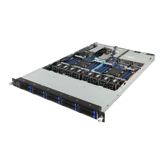
Chapter 2 System Appearance Front View HDD #0 HDD #2 HDD #4 HDD #6 HDD #8 HDD #1 HDD #3 HDD #5 HDD #7 HDD #9 Description Front Panel LEDs and buttons Front USB 3.0 ports Orange HDD Latches Support NVMe •... -
Page 18: Front Panel Led And Buttons
Front Panel LED and Buttons No. Name Color Status Description Reset Button Press the button to reset the system. Press the button server generates a NMI to the processor NMI button if the multiple-bit ECC errors occur, which effectively halt the server. -
Page 19: Rear System Lan Leds
Rear System LAN LEDs Name Color Status Description Yellow 1 Gbps data rate 1GbE Green 100 Mbps data rate Speed LED 10 Mbps data rate Link between system and 1GbE Green network or no access Link/ Blink Data transmission or receiving is occurring Activity LED No data transmission or receiving is occurring - 18 -... -
Page 20: Hard Disk Drive Leds
Hard Disk Drive LEDs HDD Present RAID SKU LED1 Locate Rebuilding Fault Access (No Access) Disk LED Green Green ON(*1) (LED on Back Panel) Amber Amber No RAID configuration Green ON(*1) Green (via HBA, ICH) Removed HDD Slot (LED on Back Panel) Amber Amber Green... -
Page 21: Chapter 3 System Hardware Installation
Chapter 3 System Hardware Installation Pre-installation Instructions Computer components and electronic circuit boards can be damaged by discharges of static electricity. Working on computers that are still connected to a power supply can be extremely dangerous. Follow the simple guidelines below to avoid damage to your computer or injury to yourself. -
Page 22: Removing Chassis Cover
Removing Chassis Cover Before you remove or install the system cover • Make sure the system is not turned on or connected to AC power. Follow these instructions to remove the rear system cover: Loosen and remove the thumbscrew securing the back cover. Push down the indentation located at the side of the back chassis Slide the cover horizontally to the back and remove the cover in the direction of the arrow. -
Page 23: Removing And Installing The Fan Duct
Removing and Installing the Fan Duct Follow these instructions to remove/install the fan duct: Lift up to remove the two fan ducts To install the fan duct, align the fan duct with the guiding groove. Push down the fan duct into chassis until its firmly seats - 22 - System Hardware Installation... -
Page 24: Installing The Cpu And Heat Sink
Installing the CPU and Heat Sink Read the following guidelines before you begin to install the CPU: • Make sure that the motherboard supports the CPU. • Always turn off the computer and unplug the power cord from the power outlet before installing the CPU to prevent hardware damage. - Page 25 - 24 - System Hardware Installation...
-
Page 26: Installing The Memory
Installing the Memory Read the following guidelines before you begin to install the memory: • Make sure that the motherboard supports the memory. It is recommended that memory of the same capacity, brand, speed, and chips be used. • Always turn off the computer and unplug the power cord from the power outlet before installing the memory to prevent hardware damage. -
Page 27: Installing A Memory
3-4-2 Installing a Memory Before installing a memory module, make sure to turn off the computer and unplug the power cord from the power outlet to prevent damage to the memory module. Be sure to install DDR4 DIMMs on this motherboard. Follow these instructions to install the Memory: Insert the DIMM memory module vertically into the DIMM slot, and push it down. -
Page 28: Installing The Pci Expansion Card
Installing the PCI Expansion Card • Voltages can be present within the server whenever an AC power source is connected. This voltage is present even when the main power switch is in the off position. Ensure that the system is powered-down and all power sources have been disconnected from the server prior to installing a PCI card. -
Page 29: Installing The Hard Disk Drive
Installing the Hard Disk Drive Read the following guidelines before you begin to install the Hard disk drive: • Take note of the drive tray orientation before sliding it out. • The tray will not fit back into the bay if inserted incorrectly. •... -
Page 30: Installing The Mezzanine Card
Installing the Mezzanine Card Follow these instructions to install a mezzanine card: Insert the mezzanine card into the system ensuring that the connector on the mezzanine card connects to the connector on the motherboard. Secure the mezzanine card to the system with three screws. System Hardware Installation - 29 -... -
Page 31: Replacing The Fan Assemblly
Replacing the FAN Assemblly Follow these instructions to replace the fan assembly: Lift up the fan assembly from the chassis. Reverse the previous steps to install the replacement fan assembly. - 30 - System Hardware Installation... -
Page 32: Replacing The Power Supply
Replacing the Power Supply Before you remove or install the system cover • Make sure the system is not turned on or connected to AC power. Follow these instructions to replace the power supply: Press the retaining clip on the right side of the power supply along the direction of the arrow. Pull up the power supply handle at the same time and pull out the power supply. -
Page 33: Cable Routing
3-10 Cable Routing Suggest Cable Suggest Cable USB cable On board SATA2 to back plane board cable (Yellow) (Orange) Front switch cable/Front LED cable On board SATA0 to back plane board cable (Pink) (Green) On board SATA1 to back plane board cable HDD back plane board power cable (Blue) (Red) - Page 34 System Hardware Installation - 33 -...
-
Page 35: Chapter 4 Motherboard Components
Chapter 4 Motherboard Components Motherboard Components 16 16 CPU1 (Secondary) Item Description HDD back plane board connector Front panel connector Front panel USB 3.0 connector TPM modue connector BMC firmware readiness LED Case open intrusion header IPMB connector OCP mezzanine connector#1 (without KR signal) Riser slot connector #1 sSATA connector #5 (for ODD/2.5"... - Page 36 SATA DOM support power connector (for sSATA connector #5) NCSI swtich OCP mezzanine connector#2 (with KR signal) Riser slot connector #2 Power supply connector#1 (primary) NVMe upgrade key (function available on select models) Power supply connector#2 (secondary) 2 x 7 Pin HDD back plane board power connector Motherboard Components - 35 -...
-
Page 37: Jumper Setting
Jumper Setting HOST_SMBUS_SEL BIOS defined ME_UPDATE Force ME update Normal [Default] PMBUS_SEL BIOS defined BIOS_PWD Clear supervisor password Normal [Default] Stop initial power on BIOS_RCVR BIOS recovery mode Normal [Default] S3_MASK Normal [Default] when BMC is not ready ME_RCVR ME recovery mode Normal [Default] DB_PLD CPLD debug mode... - Page 38 Motherboard Components - 37 -...
-
Page 39: Chapter 5 Bios Setup
Chapter 5 BIOS Setup BIOS (Basic Input and Output System) records hardware parameters of the system in the EFI on the motherboard. Its major functions include conducting the Power-On Self-Test (POST) during system startup, saving system parameters and loading operating system, etc. BIOS includes a BIOS Setup program that allows the user to modify basic system configuration settings or to activate certain system features. - Page 40 Main This setup page includes all the items in standard compatible BIOS. Advanced This setup page includes all the items of AMI BIOS special enhanced features. (ex: Auto detect fan and temperature status, automatically configure hard disk parameters.) ...
-
Page 41: The Main Menu
The Main Menu Once you enter the BIOS Setup program, the Main Menu (as shown below) appears on the screen. Use arrow keys to move among the items and press <Enter> to accept or enter other sub-menu. Main Menu Help The on-screen description of a highlighted setup option is displayed on the bottom line of the Main Menu. - Page 42 Project Name Displays the project name information. Project Version Displays version number of the BIOS setup utility. Build Date and Time Displays the date and time when the BIOS setup utility was created. BMC Information (Note) BMC Firmware Version (Note) Displays BMC firmware version information.
- Page 43 Onboard LAN Information LAN MAC Address (Note) Displays LAN MAC address information. System Date Sets the date following the weekday-month-day-year format. System Time Sets the system time following the hour-minute-second format. (Note) Functions available on selected models. - 42 - BIOS Setup...
-
Page 44: Advanced Menu
Advanced Menu The Advanced menu display submenu options for configuring the function of various hardware components. Select a submenu item, then press Enter to access the related submenu screen. BIOS Setup - 43 -... -
Page 45: Iscsi Configuration
5-2-1 iSCSI Configuration iSCSI Initiator Name Add an Attempt Press [Enter] for configuration of advanced items. Delete Attempts Press [Enter] for configuration of advanced items. Change Attempt Order Press [Enter] for configuration of advanced items. - 44 - BIOS Setup... -
Page 46: Intel(R) Virtual Raid On Cpu
5-2-2 Intel(R) Virtual RAID on CPU Intel(R) Virtual RAID on CPU Press [Enter] to manage Interl® Virtual RAID on the CPU. BIOS Setup - 45 -... - Page 47 5-2-3 Intel(R) Ethernet Connection X722 - 46 - BIOS Setup...
-
Page 48: Intel(R) Ethernet Connection X722
Intel(R) Ethernet Connection X722 for 10GBASE-T Intel(R) Ethernet Connection X722 for 10GbE NIC Configuration Press [Enter] for configuration of advanced items of the selected network device port. Blink LEDs Identifies the physical network port by blinking the associated LED. Press the numeric keys to adjust desired values. UEFI Driver Displays the technical specifications for the Network Interface Controller. - Page 49 Adapter PBA Displays the technical specifications for the Network Interface Controller. Device Name Displays the technical specifications for the Network Interface Controller. Chip Type Displays the technical specifications for the Network Interface Controller. PCI Device ID Displays the technical specifications for the Network Interface Controller. PCI Address Displays the technical specifications for the Network Interface Controller.
- Page 50 5-2-3-1 NIC Configuration Link Speed Allows for automatic link speed adjustment. Default setting is Auto Negotiated. Wake On LAN Enables power on of the system via LAN. Note that configuring Wake on LAN in the operating system does not change the value of this setting, but does override the behavior of Wake on LAN in OS controlled power states.
-
Page 51: Trusted Computing
5-2-4 Trusted Computing Configuration Security Device Support Enable/Disable the TPM support feature. Options available: Enable/Disable. Default setting is Enable. Current Status Information Displays current TPM status information. - 50 - BIOS Setup... -
Page 52: Serial Port Console Redirection
5-2-5 Serial Port Console Redirection COM1/COM2 Serial Over LAN Console Redirection (Note) Select whether to enable console redirection for specified device. Console redirection enables the users to manage the system from a remote location. Options available: Enabled/Disabled. Default setting is Disabled. Legacy Console Redirection Selects a COM port for Legacy serial redirection. - Page 53 5-2-5-1 COM1/COM2 Serial Over LAN/Legacy/Serial Port for Out-of-Band EMS Console Redirection Settings - 52 - BIOS Setup...
- Page 54 COM1/COM2 Serial Over LAN Console Redirection Settings Terminal Type Selects a terminal type to be used for console redirection. Options available: VT100/VT100+/ANSI /VT-UTF8. Default setting is ANSI. Bits per second Selects the transfer rate for console redirection. Options available: 9600/19200/38400/57600/115200. Default setting is 115200. Data Bits Selects the number of data bits used for console redirection.
- Page 55 Parity A parity bit can be sent with the data bits to detect some transmission errors. Even: parity bit is 0 if the num of 1's in the data bits is even. Odd: parity bit is 0 if num of 1's in the data bits is odd. Mark: parity bit is always 1.
- Page 56 5-2-6 SIO Configuration BIOS Setup - 55 -...
- Page 57 AMI SIO Driver Version Displays the AMI SIO driver version information. Super IO Chip Logical Device(s) Configuration [*Active*] Serial Port 1/Serial Port 2 Press [Enter] for configuration of advanced items. Serial Port 1/Serial Port 2 Configuration Use This Device When set to Enabled allows you to configure the Serial port 1/Serial port 2 settings. When set to Disabled, displays no configuration for the serial port.
- Page 58 Options available for Serial Port 2: Use Automatic Settings IO=2F8h; IRQ=3; DMA; IO=3F8h; IRQ=3, 4, 5, 7, 9, 10, 11, 12; DMA; IO=2F8h; IRQ=3, 4, 5, 7, 9, 10, 11, 12; DMA; IO=3E8h; IRQ=3, 4, 5, 7, 9, 10, 11, 12; DMA; IO=2E8h;...
-
Page 59: Pci Subsystem Settings
5-2-7 PCI Subsystem Settings PCI Bus Driver Version Displays the PCI Bus Driver version information. PCI Express Slot #1/#2/#3/#4/#5/#6/#7/#8 I/O ROM (Note) When enabled, this setting will initialize the device expansion ROM for the related PCI-E slot. Options available: Enabled/Disabled. Default setting is Enabled. Onboard LAN1 Controller (Note) Enable/Disable the onboard LAN1 devices. -
Page 60: Network Stack
5-2-8 Network Stack Network stack Enable/Disable the UEFI network stack. Options available: Enabled/DIsabled. Default setting is Enabled. Ipv4 PXE Support (Note) Enable/Disable the Ipv4 PXE feature. Options available: Enabled/DIsabled. Default setting is Enabled. Ipv4 HTTP Support (Note) Enable/Disable the Ipv4 HTTP feature. Options available: Enabled/DIsabled. -
Page 61: Csm Configuration
5-2-9 CSM Configuration Compatibility Support Module Configuration CSM Support (Note) Enable/Disable the Compatibility Support Module (CSM) support. Options available: Enabled/Disabled. Default setting is Disabled. CSM16 Module Version Displays the CSM module version information. Please note that this item is configurable when CSM Support is set to Enabled. Advanced items prompt when this item is set to Enabled. - Page 62 GateA20 Active When set to Upon Request, GA20 can be disabled using BIOS services. When set to Always, GA20 cannot be disabled; this option is useful when any RT code is executed above 1MB. Options available: Upon Request/Always. Default setting is Upon Request. Please note that this item is configurable when CSM Support is set to Enabled.
-
Page 63: Post Report Configuration
5-2-10 Post Report Configuration Post Report Configuration Error Message Report Post Error Message Enable/Disable the POST Error Message support. Options available: Enabled/Disabled. Default setting is Enabled. - 62 - BIOS Setup... -
Page 64: Nvme Configuration
5-2-11 NVMe Configuration NVMe Configuration Displays the NVMe devices connected to the system. BIOS Setup - 63 -... -
Page 65: Usb Configuration
5-2-12 USB Configuration USB Configuration USB Devices: Displays the USB devices connected to the system. XHCI Hand-off Enable/Disable the XHCI (USB 3.0) Hand-off support. Options available: Enabled/Disabled. Default setting is Enabled. USB Mass Storage Driver Support (Note) Enable/Disable the USB Mass Storage Driver Support. Options available: Enabled/Disabled. -
Page 66: Chipset Configuration
5-2-13 Chipset Configuration Restore on AC Power Loss (Note) Defines the power state to resume to after a system shutdown that is due to an interruption in AC power. When set to Last State, the system will return to the active power state prior to shutdown. When set to Stay Off, the system remains off after power shutdown. -
Page 67: Chipset Setup Menu
Chipset Setup Menu Chipset Setup menu displays submenu options for configuring the function of North Bridge and South Bridge. Select a submenu item, then press Enter to access the related submenu screen. - 66 - BIOS Setup... -
Page 68: Processor Configuration
5-3-1 Processor Configuration Processor Configuration Pre-Socket Configuration Press [Enter] for configuration of advanced items. Processor Socket/Processor ID/Processor Frequency/Processor Max Raito/ Processor Min Raio/Microcode Revision/L1 Cache RAM/L2 Cache RAM/L3 Cache RAM/ Processor 0/1 Version Displays the technical specifications for the installed processor. BIOS Setup - 67 -... - Page 69 Hyper-Threading [All] The Hyper Threading Technology allows a single processor to execute two or more separate threads concurrently. When hyper-threading is enabled, multi-threaded software applications can execute their threads, thereby improving performance. Options available: Enable/Disable. Default setting is Enable. Enable Intel(R) TXT Enables ord isables the Intel Trusted Execution Technology support function.
- Page 70 5-3-1-1 Pre-Socket Configuration BIOS Setup - 69 -...
- Page 71 CPU Socket 0/1 Configuration Press [Enter] for configuration of advanced items. Core Disable Bitmap(Hex) (for CPU socket 0/1) Number of Cores to enable. 0 means all cores. FFFFFFF means to disable all cores. The maximum value depends on the number of CPUs available. Press the numeric keys to adjust desired values. - 70 - BIOS Setup...
-
Page 72: Common Refcode Configuration
5-3-2 Common RefCode Configuration Common RefCode Configuration MMIO High Base Selects the MMIO High Base setting. Options available: 56T/40T/24T/16T/4T/1T. Default setting is 56T. MMIO High Granularity Size Selects the allocation size used to assign mmioh resources. Total mmioh space can be up to 32xgranularity. - Page 73 5-3-3 UPI Configuration - 72 - BIOS Setup...
-
Page 74: Upi Configuration
UPI General Configuration Press [Enter] to change the UPI general settings. UPI Status Press [Enter] to view the UPI status. Link Frequency Select Selects the UPI link frequency. Options available: 9.6GB/10.4GB/Auto. Default setting is Auto. BIOS Setup - 73 -... -
Page 75: Memory Configuration
5-3-4 Memory Configuration Integrated Memory Controller (iMC) Enforce POR When set to Enable, the system enforces Plan Of Record restrictions for DDR4 frequency and voltage programming. When set to Auto, the system sets it to the MRC default settings. Options available: Auto/POR/Disable. Default setting is Enable. Memory Frequency Configures the memory frequency. - Page 76 Interleave NVDIMMs Controls if NVDIMMs are interleaved together or not. Options available: Enable/Disable. Default setting is Disable. Memory Topology Press [Enter] for configuration of advanced items. Memory RAS Configuration Press [Enter] for configuration of advanced items. BIOS Setup - 75 -...
- Page 77 5-3-4-1 Memory Topology - 76 - BIOS Setup...
- Page 78 5-3-4-2 Memory RAS Configuration Memory RAS Configuration Setup RAS Type Displays the RAS type. Static Virtual Lockstep Mode Enable/Disable the Static Virtual Lockstep mode. Options available: Disable/Enable. Default setting is Disable. Mirror Mode Mirror Mode will set entire 1LM/2LM memory in system to be mirrored, consequently reducing the memory capacity by half.
-
Page 79: Iio Configuration
5-3-5 IIO Configuration IIO Configuration Intel® VT for Directed I/O (VT-d) Press [Enter] for configuration of advanced items. Inter® VMD technology Press [Enter] for configuration of advanced items. - 78 - BIOS Setup... - Page 80 5-3-5-1 Intel® VT for Directed I/O (VT-d) Intel® VT for Directed I/O (VT-d) Intel® VT for Directed I/O (VT-d) Enable/Disable the Intel VT for Directed I/O (VT-d) support function by reporting the I/O device assignment to VMM through DMAR ACPI Tables. Options available: Enable/Disable.
- Page 81 5-3-5-2 Intel® VMD Technology Intel® VMD technology Intel® VMD Configuration Enable/Disable the Intel VMD support function. Options available: Enable/Disable. Default setting is Disable. - 80 - BIOS Setup...
-
Page 82: Advanced Power Management Configuration
5-3-6 Advanced Power Management Configuration Advanced Power Management Configuration CPU P State Control Press [Enter] for configuration of advanced items. Hardware PM State Control Press [Enter] to configure the Hardware P-State setting. CPU C State Control Press [Enter] for configuration of advanced items. Package C State Control Press [Enter] to configure the Package C State limit. - Page 83 5-3-6-1 CPU P State Control SpeedStep (Pstates) Conventional Intel SpeedStep Technology switches both voltage and frequency in tandem between high and low levels in response to processor load. Options available: Enable/Disable. Default setting is Enable. Turbo Mode When this item is enabled, the processor will automatically ramp up the clock speed of 1-2 of its processing cores to improve its performance.
- Page 84 5-3-6-2 Hardware PM State Control Hardware P-States When this item is disabled, the processor hardware chooses a P-state based on OS Request (Legacy P-States). In Native mode, the processor hardware chooses a P-state based on OS guidance. In Out of Band mode, the processor hardware autonomously chooses a P-state (with no OS guidance). Options available: Disable/Native Mode/Out of Band Mode/Native Mode with No Legacy Support.
- Page 85 5-3-6-3 CPU C State Control Autonomous Core C-State Enable/Disable the Autonomous Core C-State Control. Options available: Enable/Disable. Default setting is Disable. CPU C6 Report Allows you to determine whether to let the CPU enter C6 mode in system halt state. When enabled, the CPU core frequency and voltage will be reduced during system halt state to decrease power consumption.
- Page 86 5-3-6-4 Package C State Control Package C-State Configures the state for the C-State package limit. Options available: C0/C1 state/C2 state/C6(non Retention) state/C6(Retention) state/No Limit/Auto. Default setting is Auto. BIOS Setup - 85 -...
- Page 87 5-3-6-5 CPU-Advanced PM Tuning Energy Perf BIAS Enters the Energy Perf BIAS submenu. Power Performance Tuning (Note) Tunes the Power Performance Configuration mode. When enabled, uses IA32_ENERGY_PERF_BIAS input from the core. When disabled, uses alternate performance BIAS input from ENERGY_PERF_ BIAS_CONFIG.
- Page 88 ENERGY_PERF_BIAS_CFG mode Selects the Energy Performance Bias Configuration Mode. Options available: Performance/Balanced Performance/Balanced Power/Power. Default setting is Balanced Performance. Please note that this item is configurable when Power Performance Tuning is set to BIOS Con- trols EPB. BIOS Setup - 87 -...
-
Page 89: Pch Configuration
5-3-7 PCH Configuration PCH Configuration PCH SATA Configuration Press [Enter] for configuration of advanced items. PCH sSATA Configuration Press [Enter] for configuration of advanced items. - 88 - BIOS Setup... - Page 90 5-3-7-1 PCH SATA Configuration PCH SATA Configuration SATA Controller(s) Enable/Disable SATA controller. Options available: Enable/Disable. Default setting is Enable. Configure SATA as Configure on chip SATA type. AHCI Mode: When set to AHCI, the SATA controller enables its AHCI functionality. Then the RAID function is disabled and cannot be access the RAID setup utility at boot time.
- Page 91 RAID Mode: When set to RAID, the SATA controller enables both its RAID and AHCI functions. You will be allows access the RAID setup utility at boot time. Options available: AHCI/RAID. Default setting is AHCI. Alternate Device ID on RAID (Note 1) Enable/Disable Alternate Device ID on RAID mode.
- Page 92 5-3-7-2 PCH sSATA Configuration PCH sSATA Configuration sSATA Controller(s) Enable/Disable sSATA controller. Options available: Enable/Disable. Default setting is Enable. Configure sSATA as Configure on chip SATA type. AHCI Mode: When set to AHCI, the SATA controller enables its AHCI functionality. Then the RAID function is disabled and cannot be access the RAID setup utility at boot time.
- Page 93 RAID Mode: When set to RAID, the SATA controller enables both its RAID and AHCI functions. You will be allows access the RAID setup utility at boot time. Options available: AHCI/RAID. Default setting is AHCI. Alternate Device ID on RAID (Note 1) Enable/Disable Alternate Device ID on RAID mode.
-
Page 94: Miscellaneous Configuration
5-3-8 Miscellaneous Configuration Miscellaneous Configuration Active Video Selects the active video type. Options available: Auto/Onboard Device/PCIE Device. Default setting is Auto. BIOS Setup - 93 -... -
Page 95: Server Me Configuration
5-3-9 Server ME Configuration General ME Configuration Operational Firmware Version Displays Operational Firmware version information. ME Firmware Status #1/#2 Displays ME Firmware status information. Current State (for ME Firmware) Displays ME Firmware current status information. Error Code (for ME Firmware) Displays ME Firmware status error code. -
Page 96: Runtime Error Logging
5-3-10 Runtime Error Logging Runtime Error Logging System Errors Enable/Disable system error logging function. Options available: Enable/Disable. Default setting is Enable. S/W Error Injection Support Enable/Disable software injection error logging function. Options available: Enable/Disable. Default setting is Disable. Whea Settings Press [Enter] for configuration of advanced items. - Page 97 5-3-10-1 Whea Settings WHEA Support (Windows Hardware Error Architecture) Enable/Disable WHEA Support. Options available: Enable/Disable. Default setting is Enable. - 96 - BIOS Setup...
- Page 98 5-3-10-2 Memory Error Enabling Memory Error Enable/Disable Memory Error. Options available: Enable/Disable. Default setting is Enable. Memory Corrected Error Enable/Disable Memory Corrected Error. Options available: Enable/Disable. Default setting is Enable. Uncorrected Error disable Memory Enable/Disable the Memory that triggers Uncorrected Error. Options available: Enable/Disable.
- Page 99 5-3-10-3 PCIe Error Enabling Corrected Error Enables and escalates Correctable Errors to error pins. Options available: Enable/Disable. Default setting is Enable. Uncorrected Error Enables and escalates Uncorrectable/Recoverable Errors to error pins. Options available: Enable/Disable. Default setting is Enable. Fatal Error Enable Enables and escalates Fatal Errors to error pins.
-
Page 100: Server Management Menu
Server Management Menu FRB-2 Timer Enable/Disable FRB-2 timer (POST timer). Options available: Enabled/Disabled. Default setting is Disabled. FRB-2 Timer timeout Configure the FRB2 Timer timeout. Options available: 3 minutes/4 minutes/5 minutes/6 minutes. Default setting is 6 minutes. Please note that this item is configurable when FRB-2 Timer is set to Enabled. FRB-2 Timer Policy Configure the FRB2 Timer policy. -
Page 101: System Event Log
System Event Log Press [Enter] for configuration of advanced items. View FRU Information Press [Enter] to view the advanced items. BMC network configuration Press [Enter] for configuration of advanced items. IPv6 BMC Network Configuration Press [Enter] for configuration of advanced items. - 100 - BIOS Setup... - Page 102 5-4-1 System Event Log Enabling/Disabling Options SEL Components Change this item to enable or disable all features of System Event Logging during boot. Options available: Enabled/Disabled. Default setting is Enabled. Erasing Settings Erasing SEL Choose options for erasing SEL. Options available: No/Yes, On next reset/Yes, On every reset. Default setting is No. When SEL is Full Choose options for reactions to a full SEL.
- Page 103 5-4-2 View FRU Information The FRU page is a simple display page for basic system ID information, as well as System product information. Items on this window are non-configurable. (Note) The model name will vary depends on the product you purchased - 102 - BIOS Setup...
- Page 104 5-4-3 BMC Network Configuration Select NCSI and Dedicated LAN Switch NCSI and dedicated LAN and send KCS command. Options available: Do Nothing/Mode1 (Dedicated)/Mode2(NSCI)/Mode3 (Failover). Default setting is Mode1 (Dedicated). Lan Channel 1 Configuration Address source Select to configure LAN channel parameters statically or dynamically (DHCP). Do nothing option will not modify any BMC network parameters during BIOS phase.
- Page 105 5-4-4 IPv6 BMC Network Configuration IPv6 BMC Lan Channel 1 IPv6 BMC Lan Option Enable/Disable IPv6 BMC LAN channel function. When this item is disabled, the system will not modify any BMC network during BIOS phase. Options available: Enable/Disable. Default setting is Enable. IPv6 BMC Lan IP Address Source Select to configure LAN channel parameters statically or dynamically (by BIOS or BMC).
-
Page 106: Security Menu
Security Menu The Security menu allows you to safeguard and protect the system from unauthorized use by setting up access passwords. There are two types of passwords that you can set: • Administrator Password Entering this password will allow the user to access and change all settings in the Setup Utility. •... -
Page 107: Secure Boot
5-5-1 Secure Boot The Secure Boot submenu is applicable when your device is installed the Windows 8 (or above) operating ® system. System Mode Displays the system is in User mode or Setup mode. Secure Boot Displays the Secure Boot function is actived or not actived. Vendor Keys Displays the Vendor Keys function is actived or not actived. - Page 108 5-5-1-1 Key Management Provision Factory Defaults Allows to provision factory default Secure Boot keys when system is in Setup Mode. Options available: Enabled/Disabled. Default setting is Disabled. Install Factory Default Keys Installs all factory default keys. It will force the system in User Mode. Options available: Yes/No.
- Page 109 Forbidden Signatures (DBX) Displays the current status of the Forbidden Signature Database. Press [Enter] to configure a new dbx or load additional dbx from storage devices. Options available: Set New/Append. Authorized TimeStamps (DBT) Displays the current status of the Authorized TimeStamps Database. Press [Enter] to configure a new DBT or load additional DBT from storage devices.
-
Page 110: Boot Menu
Boot Menu The Boot menu allows you to set the drive priority during system boot-up. BIOS setup will display an error message if the legacy drive(s) specified is not bootable. Boot Configuration Setup Prompt Timeout Number of seconds to wait for setup activation key. 65535 (0xFFFF) means indefinite waiting. Press the numeric keys to input the desired values. -
Page 111: Uefi Network Drive Bbs Priorities
UEFI Network Drive BBS Priorities Press [Enter] to configure the boot priority. UEFI Application Boot Priorities Press [Enter] to configure the boot priority. - 110 - BIOS Setup... - Page 112 5-6-1 UEFI NETWORK Drive BBS Priorities The UEFI network drive BBS priorities submenu allows you to specify the boot device priority from the available UEFI network drives during system boot-up. BIOS setup will display an error message if the legacy drive(s) specified is not bootable.
- Page 113 5-6-2 UEFI Application Boot Priorities The UEFI application boot priorities submenu allows you to specify the boot device priority from the available UEFI applications during system boot-up. BIOS setup will display an error message if the legacy drive(s) specified is not bootable. - 112 - BIOS Setup...
-
Page 114: Save & Exit Menu
Save & Exit Menu The Exit menu displays the various options to quit from the BIOS setup. Highlight any of the exit options then press Enter. Save Options Save Changes and Exit Saves changes made and closes the BIOS setup. Options available: Yes/No. - Page 115 Default Options Restore Defaults Loads the default settings for all BIOS setup parameters. Setup Defaults are quite demanding in terms of resources consumption. If you are using low-speed memory chips or other kinds of low-performance components and you choose to load these settings, the system might not function properly. Options available: Yes/No.
-
Page 116: Bios Post Codes
BIOS POST Codes 5-8-1 AMI Standard - PEI PEI_CORE_STARTED 0x10 PEI_CAR_CPU_INIT 0x11 PEI_CAR_NB_INIT 0x15 PEI_CAR_SB_INIT 0x19 PEI_MEMORY_SPD_READ 0x2B PEI_MEMORY_PRESENCE_DETECT 0x2C PEI_MEMORY_TIMING 0x2D PEI_MEMORY_CONFIGURING 0x2E PEI_MEMORY_INIT 0x2F PEI_MEMORY_INSTALLED 0x31 PEI_CPU_INIT 0x32 PEI_CPU_CACHE_INIT 0x33 PEI_CPU_AP_INIT 0x34 PEI_CPU_BSP_SELECT 0x35 PEI_CPU_SMM_INIT 0x36 PEI_MEM_NB_INIT 0x37 PEI_MEM_SB_INIT 0x3B PEI_DXE_IPL_STARTED... - Page 117 DXE_SB_INIT 0x70 DXE_SB_SMM_INIT 0x71 DXE_SB_DEVICES_INIT 0x72 DXE_ACPI_INIT 0x78 DXE_CSM_INIT 0x79 DXE_BDS_STARTED 0x90 DXE_BDS_CONNECT_DRIVERS 0x91 DXE_PCI_BUS_BEGIN 0x92 DXE_PCI_BUS_HPC_INIT 0x93 DXE_PCI_BUS_ENUM 0x94 DXE_PCI_BUS_REQUEST_RESOURCES 0x95 DXE_PCI_BUS_ASSIGN_RESOURCES 0x96 DXE_CON_OUT_CONNECT 0x97 DXE_CON_IN_CONNECT 0x98 DXE_SIO_INIT 0x99 DXE_USB_BEGIN 0x9A DXE_USB_RESET 0x9B DXE_USB_DETECT 0x9C DXE_USB_ENABLE 0x9D DXE_IDE_BEGIN 0xA0 DXE_IDE_RESET 0xA1 DXE_IDE_DETECT...
-
Page 118: Ami Standard - Error
5-8-3 AMI Standard - ERROR PEI_MEMORY_INVALID_TYPE 0x50 PEI_MEMORY_INVALID_SPEED 0x50 PEI_MEMORY_SPD_FAIL 0x51 PEI_MEMORY_INVALID_SIZE 0x52 PEI_MEMORY_MISMATCH 0x52 PEI_MEMORY_NOT_DETECTED 0x53 PEI_MEMORY_NONE_USEFUL 0x53 PEI_MEMORY_ERROR 0x54 PEI_MEMORY_NOT_INSTALLED 0x55 PEI_CPU_INVALID_TYPE 0x56 PEI_CPU_INVALID_SPEED 0x56 PEI_CPU_MISMATCH 0x57 PEI_CPU_SELF_TEST_FAILED 0x58 PEI_CPU_CACHE_ERROR 0x58 PEI_CPU_MICROCODE_UPDATE_FAILED 0x59 PEI_CPU_NO_MICROCODE 0x59 PEI_CPU_INTERNAL_ERROR 0x5A PEI_CPU_ERROR 0x5A PEI_RESET_NOT_AVAILABLE 0x5B... -
Page 119: Intel Upi Post Codes
5-8-4 Intel UPI POST Codes Initialize KTIRC inuput structure default values 0xA0 Collect info such as SBSP, Boot Mode, Reset type etc 0xA1 Setup IO SADs in SBSP to access the config space 0xA2 Setup up minimum path between SBSP & other sockets 0xA3 Add the node to the tree Parse the LEP of the discovered socket... -
Page 120: Intel Mrc Post Codes
Unsupported topology 0xDC RC Behavior: System Halt SBSP cannot find KPIRC TXEQ Parameters for this 0xDD link in GetSocketLinkEparams(). No retry. RC Behavior: System Halt 5-8-6 Intel MRC POST Codes Detect DIMM population 0xB0 Set DDR frequency 0xB1 Gather remaining SPD data 0xB2 Program registers on the memory controller level 0xB3... -
Page 121: Intel Pm Post Codes
5-8-8 Intel PM POST Codes Start of PPM structure initialization 0xD0 PPM CSR programming 0xD1 PPM MSR programming 0xD2 Start of PState transition init 0xD3 PPM exit 0xD4 PPM On ready to boot event 0xD5 5-8-9 Intel PM POST Codes Start of IIO early Initialization 0xE0 Pre Link training... -
Page 122: Bios Post Beep Code (Ami Standard)
BIOS POST Beep code (AMI standard) 5-9-1 PEI Beep Codes # of Beeps Description Memory not Installed. Memory was installed twice (InstallPeiMemory routine in PEI Core called twice) Recovery started DXEIPL was not found DXE Core Firmware Volume was not found Recovery failed S3 Resume failed Reset PPI is not available... -
Page 123: Bios Recovery Instruction
5-10 BIOS Recovery Instruction The system has an embedded recovery technique. In the event that the BIOS becomes corrupt the boot block can be used to restore the BIOS to a working state. To restore your BIOS, please follow the instructions listed below: Recovery Instruction: Change xxx.ROM to amiboot.rom.
Need help?
Do you have a question about the R181-2A0 and is the answer not in the manual?
Questions and answers