Table of Contents
Advertisement
Quick Links
Installation Manual
Please file and use this manual together with the service manual for Model No. CU-2E18NBU and CU-5E36QBU, Order No.
PHAAM1111120A1 and PAPAMY1312037CE.
This service information is designed for experienced repair technicians only and is not designed for use by the general public.
It does not contain warnings or cautions to advise non-technical individuals of potential dangers in attempting to service a product.
Products powered by electricity should be serviced or repaired only by experienced professional technicians. Any attempt to
service or repair the products dealt with in this service information by anyone else could result in serious injury or death.
In order to avoid frostbite, be assured of no refrigerant leakage during the installation or repairing of refrigerant circuit.
AUTO
FAN
SPEED
HEAT
AIR
COOL
SWING
DRY
FAN
CS-E9RKUAW
O FF/ O N
O FF/ O N
AUTO
ECONAVI
COMFORT
M O D E
T E M P
T E M P
AIR SWING
CS-E12RKUAW
POWERFUL/
/
QUIET
FAN SPEED
T IM E R
T IM E R
O N
O N
SET
SET
1
1
2
2
3
3
O FF
O FF
C A N C E L
C A N C E L
AC
RC
CS-E18RKUAW
SET CHECK CLOCK
CHECK
RESET
CS-E24RKUAW
AUTO
FAN
HEAT
SPEED
COOL
DRY
AIR
FAN
SWING
O FF/ O N
O FF/ O N
AUTO
ECONAVI
COMFORT
M O D E
T E M P
T E M P
POWERFUL/
/
AIR SWING
QUIET
FAN SPEED
T IM E R
T IM E R
O N
O N
SET
SET
1
1
2
2
3
3
O FF
O FF
C A N C E L
C A N C E L
AC
RC
SET CHECK CLOCK
CHECK
RESET
WARNING
PRECAUTION OF LOW TEMPERATURE
Order No: PAPAMY1501049CE
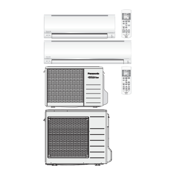
Indoor Unit
© Panasonic Corporation 2015.
Outdoor Unit
CU-E9RKUA
CU-E12RKUA
CU-E18RKUA
CU-E24RKUA
Destination
USA
Canada
Advertisement
Table of Contents

Subscribe to Our Youtube Channel
Related Manuals for Panasonic E18RKUA


Summary of Contents for Panasonic E18RKUA
- Page 1 PRECAUTION OF LOW TEMPERATURE In order to avoid frostbite, be assured of no refrigerant leakage during the installation or repairing of refrigerant circuit. © Panasonic Corporation 2015.
-
Page 2: Installation Instruction (E9Rk And E12Rk)
11. Installation Instruction (E9RK and E12RK) 11.1 Select the Best Location 11.1.3 Indoor/Outdoor Unit Installation Diagram 11.1.1 Indoor Unit Do not install the unit in excessive oil fume area Piping direction Do not bend up (Front side) drain hose such as kitchen, workshop and etc. Right There should not be any heat source or steam Rear... -
Page 3: Indoor Unit
11.2 Indoor Unit 11.2.1 How to Fix Installation Plate The mounting wall shall be strong and solid enough to prevent it from the vibration. Wall Wall Wall More than 1 More than 1 Indoor unit More than 2 screw " (128 mm) "... -
Page 4: Indoor Unit Installation
11.2.3 Indoor Unit Installation Do not turn over the unit without it’s shock absorber during pull out the piping. It may cause intake grille damage. Use shock absorber during pull out the piping to protect the intake grille from damage. Piping Piping Intake grille... -
Page 5: Connect The Cable To The Indoor Unit
Replace the drain hose Rear view for left piping installation Connection cable Piping More than 37 " Drain hose (950 mm) Drain hose Drain hose Connection Drain cap cable Sleeve for piping hole Adjust the piping slightly downwards. • • How to pull the piping and drain hose out, in case of embedded piping. -
Page 6: Cutting And Flaring The Piping
11.2.5 Wiring Stripping and connecting requirement Wire stripping Conductor Conductor Conductor not fully inserted over inserted fully inserted Indoor/outdoor connection terminal board " (5 mm) or more No loose strand ACCEPT PROHIBITED PROHIBITED when inserted (gap between wires) RISK OF FIRE JOINING OF WIRES MAY CAUSE WARNING... -
Page 7: Install The Outdoor Unit
11.3 Outdoor Unit 11.3.1 Install the Outdoor Unit After selecting the best location, start installation according to indoor/outdoor unit installation diagram. Fix the unit on concrete or rigid frame firmly and horizontally by bolt nut (ø13/32" (ø10 mm)). When installing at roof, please consider strong wind and earthquake. Please fasten the installation stand firmly with bolt or nails. -
Page 8: Evacuation Of The Equipment
11.3.2.3 Connecting the piping to outdoor multi Decide piping length and then cut by using pipe cutter. Remove burrs from cut edge. Make flare after inserting the flare nut (locate at valve) onto the copper pipe. Align center of piping to valve and then tighten with torque wrench to the specified torque as stated in the table. Hall Union Male side Female side... -
Page 9: Connect The Cable To The Outdoor Unit
11.3.3.1 Connect the Cable to the Outdoor Unit 1. Remove Top panel. 2. Remove Control Board Cover (Resin and Metal). Top Panel 3. Remove Plugs. Power Supply 4. Fix the conduit connectors to the knockout Control Board Wires holes with lock-nuts, then secure them against Metal Cover Lock Nuts Control Board... -
Page 10: Installation Instruction (E18Rk And E24Rk)
E24RKUA 24000 15.88 mm) Example: For E18RKUA If the unit is installed at 41 ft (12.5 m) distance, the quantity of additional refrigerant should be 2.46 oz (62.5 g) ..(41 - 32.8) ft x 0.3 oz/ft = 2.46 oz. - Page 11 Dimension Model " " " " " " E18RKUA, E24RKUA (590 mm) (82 mm) (539 mm) (532 mm) (169 mm) (219 mm) The center of installation plate should be at more than at right and left of the wall.
- Page 12 12.2.3 Indoor Unit Installation Do not turn over the unit without it’s shock absorber during pull out the piping. It may cause intake grille damage. Use shock absorber during pull out the piping to protect the intake grille from damage. Piping Piping Intake grille...
- Page 13 Replace the drain hose Rear view for left piping installation Connection cable Piping More than 45 " Drain hose (1150 mm) Drain hose Drain hose Connection Drain cap cable Sleeve for piping hole Adjust the piping slightly downwards. • • How to pull the piping and drain hose out, in case of embedded piping.
- Page 14 12.2.5 Wiring Stripping and connecting requirement Wire stripping Conductor Conductor Conductor not fully inserted over inserted fully inserted Indoor/outdoor connection terminal board " (5 mm) or more No loose strand ACCEPT PROHIBITED PROHIBITED when inserted (gap between wires) RISK OF FIRE JOINING OF WIRES MAY CAUSE WARNING...
- Page 15 Fix the unit on concrete or rigid frame firmly and horizontally by bolt nut ø13/32" (ø10 mm). When installing at roof, please consider strong wind and earthquake. Please fasten the installation stand firmly with bolt or nails. Model E18RKUA, 24-1/8" 5 5/32" 5/8"...
- Page 16 Align center of piping to valve and then tighten with torque wrench to the specified torque as stated in the table. Male side Female side Hall Union Flare Nut Applicable to Liquid side of (Auxiliary pipe) (Connection pipe) CS-E18RKUA CS-E24RKUA Wrench (Adjustable Wrench) Torque Wrench for Flare Nut Hall Union Flare Nut Pipe Size...
- Page 17 12.3.3.1 Connect the Cable to the Outdoor Unit 1. Remove control board cover (Resin and Metal). 2. Remove particular plate. 3. Remove plugs. 4. Fix the conduit connectors to the knockout holes with lock-nuts, then secure them against the side panel. 5.
Need help?
Do you have a question about the E18RKUA and is the answer not in the manual?
Questions and answers