
Subscribe to Our Youtube Channel
Related Manuals for NARGESA C2006


Summary of Contents for NARGESA C2006
- Page 1 HYDRAULIC SHEAR C2006 INSTRUCTIONS BOOK PRADA NARGESA, S.L Ctra. de Garrigàs a Sant Miquel s/n · 17476 Palau de Santa Eulàlia (Girona) SPAIN Tel. +34 972568085 · nargesa@nargesa.com · www.nargesa.com...
- Page 2 Thank you for choosing our machines www.nargesa.com...
-
Page 3: Table Of Contents
5.10. Program management ....................22 5.11. Gauge adjustment ...................... 24 5.12. Blade adjustment ..................... 26 5.13. Lateral length of the cut ..................... 27 5.14. General emergency ....................27 5.15. Photocell interruption …………................... 29 5.16. Pump thermal protection .................... 29 C2006 HYDRAULIC SHEAR INSTRUCTIONS BOOK... - Page 4 5.18. Input/output monitoring ....................31 5.19. Material management ....................32 5.20. Import/export parameters, materials and programs ..........33 5.21. Remote service …………………………………………………………………………….. 34 5.22. Touch screen calibration ……………..…………………………………………………… 36 6. WARNINGS ..........................37 7. ACCESORIES .......................... 38 TECHNICAL ANNEXES C2006 HYDRAULIC SHEAR INSTRUCTIONS BOOK...
-
Page 5: Characteristics Of The Machine
The C2006 is according to the European regulations and normative for the manufacturing of machinery. PRADA NARGESA S. L is not liable for any damage that might occur due to misuse or failure by users to comply with the safety standards. -
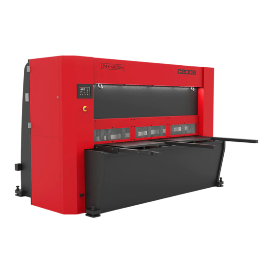
Page 6: Identification Of The Machine
1.4. Identification of the machine Laser Rammers Commands control Polycarbonate Front protection Screws to level the machien Lifting spot Power motor Side protections Stands for the entrance of the metal sheet Safety Photocell C2006 HYDRAULIC SHEAR INSTRUCTIONS BOOK... -
Page 7: General Features
4 mm Nº of hammers 10 units Cutting length 2030 mm Neck 190 mm Gauge displacement 700 mm Strokes per minute 10 strokes Position accuracy and repeatibility +/- 0,1 mm Dimensions 2865x2360x1770 mm Weight 5100 Kg C2006 HYDRAULIC SHEAR INSTRUCTIONS BOOK... -
Page 8: Description Of Safety Devices
1.6. Description of safety devices The fixed safety devices the guillotine C2006 has are lateral to avoid any handling, the front protection avoids from acceding to the rammers side, Protections in the back side of the machine covering the belts and pulley of the back top, the outet ramp for the material and the upper protection cover of the piston moveable part. -
Page 9: Transportation And Storage
* Temperature from -25 to 55ºC or 75ºC for a length of time not exceeding 24h (these must be considered storage conditions) * It is advisable not to pile up machines or heavy objects on top of it C2006 HYDRAULIC SHEAR INSTRUCTIONS BOOK... -
Page 10: Manintenance
Once the oil has been changed, it is necessary to start up the machine and activate the pedal in intermittence by increasing the pressure time gradually until the circuit is full. Oil dipstick Oil level sight-glass Drain plug C2006 HYDRAULIC SHEAR INSTRUCTIONS BOOK... -
Page 11: Lubrication Of Bolts
In order to attain the maintenance in the lateral lubrication points of the machine, we raise the folding group to its highest point. We stop the machine and proceed to the lubricate the indicated parts. Lubricate all guides greasers every month. Side view of the machine C2006 HYDRAULIC SHEAR INSTRUCTIONS BOOK... -
Page 12: Lubrication Of The Gauge Spindles
Repeat these movements 2 or 3 times, until the grease covers the spindles uniformly. Lubricate the top spindles weekly with grease or oil. Lower view of the machine C2006 HYDRAULIC SHEAR INSTRUCTIONS BOOK... -
Page 13: Instalacinstallment And Start Up
Picture 6. Working site C2006 HYDRAULIC SHEAR INSTRUCTIONS BOOK... -
Page 14: Admissible Outer Conditions
4.4 Connection to power supply The C2006 shears are equipped with two three-phase 230/400 V motors: a 0.37 kW motor for the gauge, and a 5.5 kW star-connected motor which requires a single 240V or 400V power supply. If the line voltage is not as indicated, then the motor coil connection and the gauge motor variable frequency drive (VFD) con- nection shall be changed. -
Page 15: Handling Book
5.1. Introduction This manual is designed for the user of the Guillotine C2006, since it has got important information about the use of it and the peculiar features of the machine. Therefore it is advisable to follow step by step the points detailed in this book so a good understanding of its performance could be achieved. -
Page 16: Feeding Of The Guillotine
Once the shears have started up and are in Stand-by mode, they are activated following the steps below in order to start operations. To proceed properly press . If the power source has recently been connected, the X and Y axes need to be synchronised by pressing C2006 HYDRAULIC SHEAR INSTRUCTIONS BOOK... - Page 17 The following message will appear once the Homing cycle has finalised. Cuts can be done manually from this point on by simply entering the information on the required cut. To input the cut measurements, press the corresponding button and the following screen will appear. C2006 HYDRAULIC SHEAR INSTRUCTIONS BOOK...
- Page 18 Once in this position, the sheet has been cut and the blade has reached the base. However, the blade will not be raised until the operator releases the pedal. If the operator releases the pedal, the blade will move vertically until it reaches the upper rest position. C2006 HYDRAULIC SHEAR INSTRUCTIONS BOOK...
-
Page 19: Gauge Retraction
The function is disabled by pressing (X) again, and the image will go back to being transparent. Once activated, the machine will behave as follows: After entering all the cut data and activating this function. The gauge retraction can be enabled in both single and continuous mode. C2006 HYDRAULIC SHEAR INSTRUCTIONS BOOK... -
Page 20: Light
. The laser light is turned on and generates a laser cutting line. The laser is very useful for cutting parts that are not square, or when making cuts that do not reach the end position. Press the button to turn the laser off. C2006 HYDRAULIC SHEAR INSTRUCTIONS BOOK... -
Page 21: Calculator
The result is now displayed on the main operating screen. 5.9. Automatic mode Press the key that appears on the screen to active automatic mode. On doing so, the information displayed on the screen changes. C2006 HYDRAULIC SHEAR INSTRUCTIONS BOOK... - Page 22 We can also specify the number of repetitions for the current program. To do so press and specify the number of repetitions for the program. C2006 HYDRAULIC SHEAR INSTRUCTIONS BOOK...
-
Page 23: Program Management
5.10. Program management Numerical control of the shears allows multiple programs to be defined which can be used in automatic mode. These programs are saved in the memory and can be loaded, changed and deleted when required. C2006 HYDRAULIC SHEAR INSTRUCTIONS BOOK... - Page 24 Create a copy of the selected program and save it with a different file name. Rename the selected program. Delete the selected program. When it has been activated, the system operates using folders, not programs. C2006 HYDRAULIC SHEAR INSTRUCTIONS BOOK...
-
Page 25: Gauge Adjustment
We should select the following icon from those displayed at the bottom of the screen. On doing so, the information displayed on the screen changes to the following. C2006 HYDRAULIC SHEAR INSTRUCTIONS BOOK... - Page 26 0.7 mm from the gauge “Zero Position”. This information can then be used to correct the gauge “Zero Position”. To do so, press the button again and when the menu window appears, press The window displayed is as follows: C2006 HYDRAULIC SHEAR INSTRUCTIONS BOOK...
-
Page 27: Blade Adjustment
Note that on doing so, the shears automatically return to the previous position by raising the upper blade up to the maximum machine opening position. C2006 HYDRAULIC SHEAR INSTRUCTIONS BOOK... -
Page 28: Lateral Length Of The Cut
The shears have two emergency stop buttons: one on the front, below the control touch screen, and another in the area above the cutting pedal. When one or both of the buttons are pressed, the machine stops immediately. The following pop-up message appears on the screen during an emergency stop situation. C2006 HYDRAULIC SHEAR INSTRUCTIONS BOOK... - Page 29 The machine cannot start operating again while this icon is present. The warning triangle indicates that the shears need to be reset, as a safety precaution. To do so, press the blue reset button and the warning icon will be removed from the notifications bar. C2006 HYDRAULIC SHEAR INSTRUCTIONS BOOK...
-
Page 30: Photocell Interruption
This message warns that the pump thermal protection needs to be reset before operating the shears. As with the previous two situations, press to remove the message. The warning icon will be displayed in the notifications bar to the right until the pump thermal protection is manually reset. C2006 HYDRAULIC SHEAR INSTRUCTIONS BOOK... -
Page 31: Alarm Management
The details of each of the alarms related to the shear operations can be checked in the history log. C2006 HYDRAULIC SHEAR INSTRUCTIONS BOOK... -
Page 32: Input/Output Monitoring
The machine has a useful tool which can be used to monitor the status of each of the inputs and outputs to and from the shears, in order to carry out a self-diagnosis. Access the monitoring menu by pressing the button and then the icon. C2006 HYDRAULIC SHEAR INSTRUCTIONS BOOK... -
Page 33: Material Management
Use the icons located at the bottom of the screen to do so. Create a new material by specifying the name and its resistance. The material name and resistance can be changed by selecting it from the table. The selected material can be removed from the table. C2006 HYDRAULIC SHEAR INSTRUCTIONS BOOK... -
Page 34: Import/Export Parameters, Materials And Programs
A back-up copy can also be saved to an external USB by selecting the USB option and pressing again. C2006 HYDRAULIC SHEAR INSTRUCTIONS BOOK... -
Page 35: Remote Service
10.10.51.110, which has been set at the factory. This also allows the machine to be serviced remotely. The remote service allows Nargesa, as the manufacturer, to remotely connect the machine in order to resolve technical incidents and to provide training courses to the end client. - Page 36 IT system versions used in the user interface. Press to activate the remote service so that the Nargesa technical support department can connect to the machine to resolve any incidents and/or provide training courses. C2006 HYDRAULIC SHEAR INSTRUCTIONS BOOK...
-
Page 37: Touch Screen Calibration
There is a cross in the centre of the screen which should be pressed for a few moments until it moves to a new position. This process is repeated at various points on the screen until the calibration process is complete. C2006 HYDRAULIC SHEAR INSTRUCTIONS BOOK... -
Page 38: Warnings
- Do not cancel any protection device provided by the machine. - NARGESA SL will not accept any responsibility if an accident occurs due to a negligent use of the machine on the operative’s side or for not bearing in mind the usage and safety rules decribed in this manual. -
Page 39: Accesories
The blades are treated by various processes, which reinforces its liability and resistance at a normal use condition. The guillotine C2006 has and upper blade and a lower blade each of them has got four exchangeable cutting corners. The adjustment between the two blades should be 0.1 mm. -
Page 40: Technical Annexes
Technical annex Hydraulic shear C2006 List of parts Detail of treaders Detail of guided gauge Detail of dirving gauge Detail of Hydraulic kit Detail of activation triangular connecting rod Detail of triangular rod Detail of cylinder Electric box Electric maps... - Page 41 A1. List of parts C2006 HYDRAULIC SHEAR INSTRUCTIONS BOOK...
- Page 42 C2006 HYDRAULIC SHEAR INSTRUCTIONS BOOK...
- Page 43 C2006 HYDRAULIC SHEAR INSTRUCTIONS BOOK...
- Page 44 C2006 HYDRAULIC SHEAR INSTRUCTIONS BOOK...
- Page 45 C2006 HYDRAULIC SHEAR INSTRUCTIONS BOOK...
- Page 46 C2006 HYDRAULIC SHEAR INSTRUCTIONS BOOK...
- Page 47 C2006 HYDRAULIC SHEAR INSTRUCTIONS BOOK...
- Page 48 C2006 HYDRAULIC SHEAR INSTRUCTIONS BOOK...
- Page 49 A2. Detail of treaders C2006 HYDRAULIC SHEAR INSTRUCTIONS BOOK A 10...
- Page 50 A3. Detail of guided gauge C2006 HYDRAULIC SHEAR INSTRUCTIONS BOOK A 11...
- Page 51 C2006 HYDRAULIC SHEAR INSTRUCTIONS BOOK A 12...
- Page 52 A4. Detail of dirving gauge C2006 HYDRAULIC SHEAR INSTRUCTIONS BOOK A 13...
- Page 53 C2006 HYDRAULIC SHEAR INSTRUCTIONS BOOK A 14...
- Page 54 A5. Detail of Hydraulic kit C2006 HYDRAULIC SHEAR INSTRUCTIONS BOOK A 15...
- Page 55 C2006 HYDRAULIC SHEAR INSTRUCTIONS BOOK A 16...
- Page 56 C2006 HYDRAULIC SHEAR INSTRUCTIONS BOOK A 17...
- Page 57 A6. Detail of activation triangular connecting rod C2006 HYDRAULIC SHEAR INSTRUCTIONS BOOK A 18...
- Page 58 A7. Detail of triangular rod C2006 HYDRAULIC SHEAR INSTRUCTIONS BOOK A 19...
- Page 59 A8. Detail of cylinder C2006 HYDRAULIC SHEAR INSTRUCTIONS BOOK A 20...
- Page 60 C2006 HYDRAULIC SHEAR INSTRUCTIONS BOOK A 21...
- Page 61 A9. Electric box C2006 HYDRAULIC SHEAR INSTRUCTIONS BOOK A 22...
- Page 62 A10. Electric maps C2006 HYDRAULIC SHEAR INSTRUCTIONS BOOK A 23...
- Page 63 C2006 HYDRAULIC SHEAR INSTRUCTIONS BOOK A 24...
- Page 64 C2006 HYDRAULIC SHEAR INSTRUCTIONS BOOK A 25...
- Page 65 C2006 HYDRAULIC SHEAR INSTRUCTIONS BOOK A 26...
- Page 66 C2006 HYDRAULIC SHEAR INSTRUCTIONS BOOK A 27...
- Page 67 C2006 HYDRAULIC SHEAR INSTRUCTIONS BOOK A 28...
- Page 68 C2006 HYDRAULIC SHEAR INSTRUCTIONS BOOK A 29...
- Page 69 C2006 HYDRAULIC SHEAR INSTRUCTIONS BOOK A 30...
- Page 70 A11. Hydraulic map C2006 HYDRAULIC SHEAR INSTRUCTIONS BOOK A 31...
- Page 71 3. Complete the form with your details and press Message Sent: confirms your data has been successfully sent to Prada Nargesa SL. Your machine has been registered and has a warranty of three years in total. Your request has been sent correctly. We will contact you right...
Need help?
Do you have a question about the C2006 and is the answer not in the manual?
Questions and answers