
Subscribe to Our Youtube Channel
Related Manuals for NARGESA MP3003 CNC


Summary of Contents for NARGESA MP3003 CNC
- Page 1 PRESS BRAKE MP3003 CNC INSTRUCTIONS BOOK PRADA NARGESA, S.L Ctra. de Garrigàs a Sant Miquel s/n 17476 PALAU DE STA. EULALIA (GIRONA) SPAIN Tel. 972 568085 - Fax 972 568320 www.nargesa.com - nargesa@nargesa.com...
- Page 2 Thank you for choosing our machines...
-
Page 3: Table Of Contents
4.4. Connection to power supply …………............... 12 5. ADJUSTMENT OF THE BACK GAUGE HANDLES ............. 13 6. FOLDING GROUP REGULATION ..................15 7. WARNINGS …………………………..……………………………………………………….…….. 16 ANNEX 1. SOFTWARE ESA S630 ANNEX 2. TECHNICAL FEATURES ANNEX 3. LASER DEVICES INSTRUCTIONS BOOK PRESS BRAKE MP3003 CNC... -
Page 4: Characteristics Of The Machine
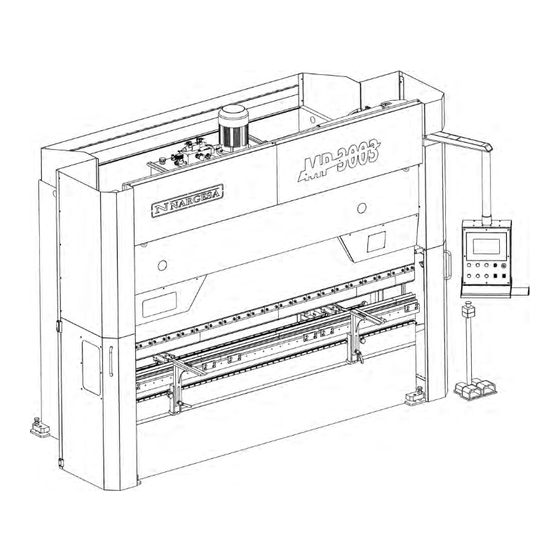
The MP3003CNC is according to the European standards and directives for the manufacturing of industrial Machinery. INSTRUCTIONS BOOK PRESS BRAKE MP3003 CNC... - Page 5 1.3. Identificación de la máquina Control panel Laser Screws to level the machine Lateral protection Sliding arms Electric motor Hydraulic container Oil emptying cap Punch Back gauge handles Die-holder INSTRUCTIONS BOOK PRESS BRAKE MP3003 CNC...
-
Page 6: General Features
Le poinçon et la matrice sont traités, ce qui assure leur fiabilité et leur résistance pour un usage normal. Les matrices possèdent plusieurs ouvertures pour les différentes épaisseurs de tôle et rayons de pli. INSTRUCTIONS BOOK PRESS BRAKE MP3003 CNC... -
Page 7: Tooling
The press brake MP3003CNC, has been designed for the use with “V” dies, punch and die holder. Other dies with upper V’s seccioned punches and press brake anvils can be also used. Please ask the manufacturer. Punch Die holder INSTRUCTIONS BOOK PRESS BRAKE MP3003 CNC... -
Page 8: Description Of Safety Devices
You can not remove the protective caps unless it is for maintenance and it should be carried out by techni- cally trained personnel. PRADA NARGESA will not responsible for damage caused by not adhering to the afore mention instructions. -
Page 9: Transportation And Storage
* Temperature -25 to 55 ° C or 75 ° C for periods not exceeding 24 hours (remember that these temperatures are in storage) * It is advisable not to stack heavy objects on the machines. * Do not disassemble for storage. INSTRUCTIONS BOOK PRESS BRAKE MP3003 CNC... -
Page 10: General Maintenance
- Grease the boulders fixing rods and piston periodically depending on use. - If the use is daily and continuous, grease each month. - Grease all guide fittings monthly. - Check the oil level of the machine. INSTRUCTIONS BOOK PRESS BRAKE MP3003 CNC... -
Page 11: Installment And Start Up
4.3 Admissible outer conditions Ambient temperature between +5 º C and +50 º C without exceeding an average temperature of +45 º C 24h Humidity between 30% and 90% non-condensing. INSTRUCTIONS BOOK PRESS BRAKE MP3003 CNC... -
Page 12: Connection To Power Supply
The gauge activation is done by a servomotor which does not require any action when making a tensión change from 400v to 230v or the other way around. The inverter configuration will have to be modified as well, as indicated in the following pictures: Configuration 400V Configuration 230V INSTRUCTIONS BOOK PRESS BRAKE MP3003 CNC... -
Page 13: Adjustment Of The Back Gauge Handles
It is completely forbidden to carry out this operation without the activation bar. Activation bar In order to proceed with the movement of the needles, we insert the activation bar in the existing slot there in the needles support. Activation bar slot INSTRUCTIONS BOOK PRESS BRAKE MP3003 CNC... - Page 14 We lower the lever and the needle will remain fixed in the new position. We take the lever off and we have the gauge ready to be used again. WARNING: Make sure we have removed the lever before starting up the press brake again. INSTRUCTIONS BOOK PRESS BRAKE MP3003 CNC...
-
Page 15: Folding Group Regulation
• Once the Folding group (Tranche) has been adjusted, fasten the fixation screw to fix the lever and pro- ceed to the assembly of the cover sheets. Adjustment lever Fixing screw CAUTION Never move the adjustment lever while the folding group is forcing against the die. INSTRUCTIONS BOOK PRESS BRAKE MP3003 CNC... -
Page 16: Warnings
Maintain a safe distance between the machine and the operator during the time the machine is running. Do not use any other tooling but the ones supplied by NARGESA. The dies that may be coupled to the machine must always be set and fixed. - Page 17 3. Complete the form with your details and press Send 4. The window Message Sent confirms your data has been successfully sent to Prada Nargesa SL. Your machine has been registered and has a warranty of three years in total.
- Page 18 Annex 1 Software ESA S630...
- Page 20 SUMMARY Notes ……………………………………………………….………………………………………… 3 1. MACHINE SETUP ………………………..…………………………...……………………….. 8 1.1. Ram reference …………………...………………………………...…………………… 8 1.2. Back-gauges axes reference ………………………………...……………………….. 8 2. PUNCHES AND DIES SETUP ………………………..……………………………………….. 9 2.1. Punches and dies list ……………..…………………………...………………………. 9 2.1.1. How to enter a new punch ……….…………………...……………………. 12 2.1.2.
- Page 21 Explanation of the symbols There may be graphic symbols alongside the text. These are used to highlight particularly relevant information. Attention: This symbol is used when failure to observe the appropriate precautions could cause slight damage to property or injury to persons Danger: This symbol is used when failure to observe the appropriate precautions or the performing of incorrect manoeuvres could cause serious damage to property or injury to persons.
- Page 22 Printing conventions To facilitate the identification of the information in this document, use is made of special printing conventions as illustrated below. Video The following conventions are used: - The names of the screen-printed button are highlighted in bold print and enclosed in square brackets. - [Ok].
- Page 23 Glossary The abbreviation of Computerised Numerical Control which indicates the apparatus governing the machine, that is, the electronic device via which the work cycles are programmed, the axes are moved, etc... It corresponds to one of the devices, the operation of which is described in this manual. Solid State Disk, also known as Flash Hard Disk, is a data saving device without any components in movement, therefore particularly suited to industrial environments.
- Page 24 The new interface of the NC Kvara S630 Touch born with a new interactive graphics on which every function is achieved at the touch of your finger. This not only because Prada Nargesa aligns well to the features most current PC environment but also want to speed up and facilitate the work of its end user.
- Page 25 - Pressing "abc" will appear in the literary characters to nominate programs, tools or to set data: Figure b) Soft Keyboard the literary characters ANEXO 1. SOFTWARE ESA S630...
-
Page 26: Machine Setup
1. MACHINE SETUP Operations to execute after powering It is obligatory reference the ram in order to access the automatic phase and execute a work program. The reference of the back-gauges axes is also mandatory. It is done automatically. This is done to avoid doubts about the correctness of the current back-gauges axes targets because they could not be correct if an axis was moved manually when the numeric control was off. -
Page 27: Punches And Dies Setup
2. PUNCHES AND DIES SETUP 2.1. Punches and dies list Comply with the following procedure to access the tools list: - Press ; to display the list of punches or list of dies. - If the list of dies appears, press again to display the punches, or vice versa. - Page 28 When the available tools are many for a fast choice can be used the scroll bar . The function buttons have the following meanings: - [New Folder] to create a new folder where save the tools - [Find] to find a tool from the punch or from the die list - [New Drawing] to completely draw the punch or the die - [New Type 1] to use a type 1 pre-set punch or [New default] to draw a pre-set die - [New Type 2] to use a type 2 pre-set punch...
- Page 29 How to erase a punch or die Allows you to eliminate a tool. Select the tool you wish to eliminate, selecting it with a finger, and comply with the procedure below: - Press the button - Press [Ok] - The selected tool will be erased. Save all tools on USB Allows you to save all the tools on USB so that they can then be transferred to another numeric control (useful when must be created backup copies).
-
Page 30: How To Enter A New Punch
2.1.1 How to enter a new punch Comply with the following procedure to enter a new punch: - Press the button ; the list of punches or list of dies will appear - If you see the dies list press again the button. -
Page 31: Punches To Draw
- Press - [New Drawing] to completely design the punch; - [New Type 1] to use a pre-set punch type 1; - [New Type 2] to use a pre-set punch type 2; - [New Type 3] to use a pre-set punch type 3. - [New Type 4] to use a type 4 pre-set punch (round punch). - Page 32 The left-hand window is the drawing window. The four right-hand windows are drawing data entry windows and respectively represent: - The polar drawing data - The Cartesian drawing data - The vertex drawing data - The arc drawing data Drawing conventions The punch must be drawn in an anticlockwise direction, remembering that the back-gauges are on the right -hand side of the punch itself.
- Page 33 How to do the drawing Supposing that the following punch must be drawn: The cursor is in Field 1 of the data entry window of the drawn tip data: - Enter the tip data as previously described - Enter the length of the second side of the tip (section l1) - Press [ENTER]: the cursor will set to the alpha Field where the angle is entered in relation to the next section - Press on the display to move to the design, using own touch (touch environment)
- Page 34 Graphic helps In relation to sections whose measurements may cause difficulties, the operator can use graphic helps allowing the angle value to be varied by ± 1° and the length to be varied by ± 1mm each time. This achieves a visual correspondence between the drawing and the real punch. To enable this feature, only valid for settings punches: - Press the button to access the menu...
-
Page 35: Pre-Set Punches
Tolerated name characters The entered name can be formed by a combination of numbers and letters (e.g. can be used the code of the punch of the catalogue). 2.1.3. Pre-set punches The pre-set punch page is presented in the form of a pre-drawn punch along with a series of data that characterize the shape of that punch. -
Page 36: How To Enter A New Die
2.2 How to enter a new die Comply with the following procedure to enter a new die: - Press the button; the list of punches or list of dies will appear. - If the list of punches appears, press button again. - Select the required type of die. -
Page 37: Dies To Draw
Press: - [New drawing] to completely design the die; - [New default] to use the data of the pre-set die. A window will be opened requesting entry of the die dimensions: Figure 10 Die dimensions Enter the die width and the die height as indicated in Figure 10 selecting with a finger the fields “width” and “hight”. - Page 38 The left-hand window is the drawing window. The four right-hand windows are drawing data entry windows and respectively represent: 1) The polar drawing data; 2) The Cartesian drawing data; 3) The V-die drawing data; 4) The square die drawing data. Drawing conventions The die must be drawn in a clockwise direction, remembering that the back-gauges are on the right-hand side of the die.
- Page 39 The cursor is in Field 1 of the polar drawing data entry window: - Enter the length corresponding to the length l1 in the field “l”, touching with a finger on the field; - Press [Ok]: the cursor will set to the α Field where the angle is entered in relation to the next section. Now define the first V-die of the die.
- Page 40 - Press [Ok]; - Enter the value of the angle a2, touching with a finger on the field; - Press [Ok]. The die drawing will form by continuing to alternatively enter the lengths and angles. More the entered measurements and angles correspond to reality, more the drawing will be correct. Entered data correction Incorrect entries may be made during drawing entry.
- Page 41 Dutch folding V-die entry (hemming V-die) The die drawing page can be used to enter Dutch folding V-die. To define one of these, it is necessary to indicate which are the lengths that determine the die closing by their movement and then draw a length squashed on both sides.
-
Page 42: Pre-Set Dies
Entry of the pneumatic flattening die support If the press has a pneumatic flattening die support, the relative data can be entered in the General Parameters Configuration page (refer to the machine parameters manual). Once the data have been entered, flattened bends can also be obtained in the graphic mode using standard dies without having to draw particular dies with bending-flattening functions. -
Page 43: Programming
3. PROGRAMMING 3.1. List of programs To enter the list of programs it is necessary to follow the steps below: - Press - The following window will appear: Figure 16 List of programs The window on the left is the program list. The central boxes contain the program data on which the cursor is positioned (on the list). - Page 44 How to copy a program This allows you to create a copy of a program with another name so that you can change it. Move onto the program you wish to copy selecting it with a finger and follow the steps below: - Press the button to open the menu.
- Page 45 Deleting all the programs This allows you to delete all the programs. Follow the steps below: - Press the button to open the menu. - Select the item 3>> Delete programs. - All the programs will be deleted (you will be asked the confirm). Programs list on the USB device This allows you to view the program list on the USB device.
-
Page 46: Entering A Numeric Program
Changing the work unit This operation can be performed in the following sequence: - Press the button to open the Program list - Press the button to open the menu - Press 5 >> Change work drive. - Select with a finger a work drive from the list Figure 17 View of the operation for changing the work unit. - Page 47 Setting the piece data A window will open for entering the program data: Figure 19 Page for entering the bends - Enter the width of the metal sheet to be bent, touching with a finger on the field and selecting [Ok]. - Enter the thickness of the metal sheet to be bent, touching with a finger on the field and selecting [Ok].
- Page 48 Figure 21 Die list page, example of die insertion - The material is calculated automatically depending on the resistance. - Enter the work station if more than one or if they are defined, otherwise leave 0. - Enter the die that will be used from the list touching with a finger on the field, scrolling the toolbar in order to choose the die and pressing the button [Insert] (the die must already have been drawn), like showed in the figure 21.
- Page 49 Work data This allows you to view the data relating to the absolute T.D.C, Mute and Pinch Point of that bend, move onto the desired bend and follow the steps below: - Press the button to open the menu. - Select the item 7>> Work Information. - A window will appear which contains the work data.
- Page 50 Correcting a radius bend Whenever a radius bend is realized it is unlikely that you will obtain a correct bend at first try: this imprecision depends on the fact that the angles that have to be bent to create the rolling are opened too far (e.g.: 170ø) and it is difficult to obtain correct bends with these angles.
-
Page 51: Entering A Graphic Program (Optional In The S630 Model)
3.3 Entering a graphic program (Optional in the S630 model) To enter a new graphic program press [New Programm] from the Editor page of a numerical program and select [New graphic]: Figure 24 New Graphic program Or it can be create from the program list pressing and [New graphic] . - Page 52 Drawing window The drawing window page will be opened. Figure 25 Drawing page of the piece. The window on the left is the drawing window. The four windows on the right are for entering the drawing data and they respectively represent: 1) The polar drawing data.
- Page 53 Figure 27 Soft Keyboard for setting the angle of the piece - By touching one of the height arrows starting from this in the clockwise direction, the next segment will be taken to different predefined angles, that is 45, 90, 135, 180, -135,-90, -45. Pressing the soft-key is possible introduce angles different from the predefined, like showed in figure 28 Figure 28 Soft Keyboard for setting not predefined angle of the piece...
- Page 54 Bend sequencing This allows you to view the sequence via which the piece must be bent. Follow the steps below: - From the AUTOMATIC graphic page press the button to open the menu. - Select the item 0>> Bending sequence. - Move among the various bends by pressing the buttons.
- Page 55 - Enter the value of the second angle (-120.0°) in the field “alfa” (value of the angle compared to the following length). -Press [Ok], the next length will be drawn in automatic mode; the length that the data refer to will be highlighted.
- Page 56 - Enter the radius of the rolling (60.0) in the field “R”, touching with a finger on the field. - Press [Ok]. - Enter the length of the rolling pitch you want to obtain in the field “P”, touching with a finger on the field. - Press [Ok], the next length will be drawn in automatic mode;...
-
Page 57: Automatic Calculation Of The Bending Sequence (Oprional In The S630 Model)
Saving the drawing At the end of the setting, press the button; a window will open in which it is necessary to enter the name of the program. After having entered the name, touching with a finger on the field, move onto the [Ok] button. 3.4 Automatic calculation of the bending sequence (Optional in the S630 model) It is possible to access the automatic calculation procedure from the drawing page of the piece by following the steps below:... - Page 58 Automatic search for the bend sequence In the automatic search, the optimal bending sequence is established by the numeric control; by pressing [Optimize] the numeric control automatically searches for the solution. Manual search for the bend sequence In the manual search, the bending sequence is established by the operator who forces the bends. The bending sequence can be completely or partially forced by the operator: in the case of the sequence only being partially forced, the remaining bends will be calculated automatically by the numeric control.
- Page 59 Simulation Once the solution has been accepted, it will be possible to simulate the bending sequence obtained in the optimisation window of the graphic program: - Press the function key [Simulate], the piece without bends, set up and ready for the first bend will be displayed.
-
Page 60: Manual Calculation Of The Bending Sequence
3.5 Manual calculation of the bending sequence (Optional in the S630 model) It is possible access the manual calculation procedure from the drawing page of the piece by following the steps below: - Press [Calculate]. Calculation window A window will open that shows the simulation of the piece to be bent, including the lower and upper part of the press-brake, the punch, the die, the stops and the piece before to being bent. - Page 61 Simulation In the optimisation window of the graphic program, once the solution has been accepted, it will be possible so simulate the bending sequence obtained: - Press the function key [Simulate], the piece without bends will be displayed, set up and ready for realize the first bend.
-
Page 62: How To Bend A Box
Changing the bend sequence Once the bend sequence has been optimised, it will be possible to change the bending sequence obtained: The operator has the possibility of moving among the various bends by pressing the buttons. To remove the bends it is necessary to press the [Bend] key in correspondence of the selected bend, remove the other bend you wish to exchange, and press [Bend] to select the new sequence desired on each bend removed. - Page 63 Automatic graphic page If the program currently selected is a calculated graphic program the automatic graphic page can be viewed by pressing [Graphic]; this page consists of three windows: The main window contains the drawing of the upper and lower parts of the machine, the drawing of the punch and the die entered in the program, the drawing of the piece before and after the bend, and the drawing of the stop.
- Page 64 - In order to have a better view of the heights of the axes, it is possible to double the size of the characters of the page. This page is enabled by pressing - To return to the page with single size characters press again.
- Page 65 The procedure can also be enabled from the AUTOMATIC page in the following manner: - Press - Press the button to position the back gauges axes. - Press the down pedal to execute the bend. - Measure the bend made in terms of bend length and angle. If the bend is not correct: - Press to access the correction data.
-
Page 66: Selection Of The Din Formula To Calculate The Stretch
Example: if a step correction is made equal to -2.0° and a piece correction equal to -1.0°, the angular correction of that step will be -3.0°. At the end of the operation for setting of the correction data: - Press - Press the button to reposition the back gauges axes (a correction may have been made to their position). - Page 67 In order to find the correct height of the end of the bend the operator can adopt various methods: - If the quota to be reached is greater than the quota of the end of the bend calculated, the new quota can only be searched using the up pedal ;...
- Page 68 Annex 2 Technical data...
- Page 70 SUMARY 1. List of parts ……..…………………………………………………………. 3 2. Hydraulic group ….…………………………….……………...………… 12 3. Upper cylinder ………….……………………………………..………. 15 4. Main cylinder …..………………………………………………..………. 17 5. Electric box ……..……………...………………………………..………. 19 6. Control panel box ……………...………………………………..………. 20 7. Electric maps ……………….……..…………………………….………. 21 8. Hydraulic map …….………………..………………………..…………. 29 ANEX 2.
-
Page 71: List Of Parts
1. List of parts ANEX 2. TECHNICAL DATA MP3003CNC... - Page 72 ANEX 2. TECHNICAL DATA MP3003CNC...
- Page 73 ANEX 2. TECHNICAL DATA MP3003CNC...
- Page 74 ANEX 2. TECHNICAL DATA MP3003CNC...
- Page 75 ANEX 2. TECHNICAL DATA MP3003CNC...
- Page 76 ANEX 2. TECHNICAL DATA MP3003CNC...
- Page 77 ANEX 2. TECHNICAL DATA MP3003CNC...
- Page 78 ANEX 2. TECHNICAL DATA MP3003CNC...
- Page 79 ANEX 2. TECHNICAL DATA MP3003CNC...
-
Page 80: Hydraulic Group
2. Hydraulic group ANEX 2. TECHNICAL DATA MP3003CNC... - Page 81 ANEX 2. TECHNICAL DATA MP3003CNC...
- Page 82 ANEX 2. TECHNICAL DATA MP3003CNC...
-
Page 83: Upper Cylinder
3. Upper cylinder ANEX 2. TECHNICAL DATA MP3003CNC... - Page 84 ANEX 2. TECHNICAL DATA MP3003CNC...
-
Page 85: Main Cylinder
4. Main cylinder ANEX 2. TECHNICAL DATA MP3003CNC... - Page 86 ANEX 2. TECHNICAL DATA MP3003CNC...
-
Page 87: Electric Box
5. Electric box ANEX 2. TECHNICAL DATA MP3003CNC... -
Page 88: Control Panel Box
6. Control panel box ANEX 2. TECHNICAL DATA MP3003CNC... -
Page 89: Electric Maps
7. Electric maps ANEX 2. TECHNICAL DATA MP3003CNC... - Page 90 ANEX 2. TECHNICAL DATA MP3003CNC...
- Page 91 ANEX 2. TECHNICAL DATA MP3003CNC...
- Page 92 ANEX 2. TECHNICAL DATA MP3003CNC...
- Page 93 ANEX 2. TECHNICAL DATA MP3003CNC...
- Page 94 ANEX 2. TECHNICAL DATA MP3003CNC...
- Page 95 ANEX 2. TECHNICAL DATA MP3003CNC...
-
Page 97: Hydraulic Map
8. Hydraulic map 1. Filter 2. Hydraulic pump 3. Electric motor 4. Pressure control valve 5. Carburator needle ASCENT 6. Solenoid NO FAST DOWN 7. Solenoid bending SLOW DOWN 8. Main solenoid 9. Speed change solenoid VERY SLOW DOWN 10. Guided anti return devide 11. - Page 98 Annex 3 Laser devices...
- Page 100 INDEX 1. General description ……………………………………………………………….. 3 2. Range of use …………………...…………………………………………………. 3 3. Aims ………..……………………………………………………………………….. 3 4. Regulation ………………………………………………………………………… 3 5. Components …………..……………………………………………………………. 3 6. Identification ………………………………….…………………………………….. 3 7. Identification of machines components ……………………………...………… 4 8. Performance ………….……………………………………………………………. 5 9. Assembling ………………………………………………………………………… 6 10.
- Page 101 The press brake laser device is a safety system with no physicla contact that allows us to be according to the regulation EN-12622:2011+A1:2013 regarding Hydraulic Press Brakes 2. Range of use The range of use of this laser devices is the Nargesa Press Brakes machines equipped with punches and “V” dies. 3. Aims The aim of this laser device is to protect the user of the machine against any risk of entrapping taht may be caused during the use of the machine.
- Page 102 7. Identification of the machine components Laser unit Laser unit Laser unit Laser unit ANNEX 3. LASER DEVICE...
- Page 103 8. Performance The laser device has got 2 units, one acting like a master and the other one acting like a slave. Each unit has an Emitter laser and a Receptor laser. These units are sinchronized between them when each unit detects the correct frame the other units is sending. If an object interferes on the laser trajectory, it will block the punch descent, but not its going up.
- Page 104 9. Assembling The assembling of Emitter –Recetor units will be made in the laterals of the Ram on the supports designed for such an effect. The assembling is made by two M8 screws (key nº 13) And a support plate. The regulation in height will be made by using the standard regulation tooling and following the indications of Anex G of the Regulation EN-12622:2011+A1:2013 we summarize next.
- Page 105 11. Test 2. Low speed stop Using the frontal part of the tooling (10mm thickness) we place it on the folding die. We actívate the des- cent of the Ram and it must stop before reaching the tooling. (Pict.7) yand next it must be able to go through the 15 mm thickness of the tooling without interfering with the punch.(Pic.7.1) 10 mm Picture 7...
- Page 106 12. Test 3. High speed stop Placing the tooling on the die and with the thickness of 35mm on the interference área of the laser, we actí- vate the stop of the ram on high speed mode and it has to stop before reaching the tooling. (Picture 8) 35 mm Picture 8 Once all these tests have been made, we finish the assembling operation of the units Emitter–...
- Page 107 Once we have the Emitter-Receptor units installed, we have to regularize the Muting zone, as it has been explained in the previous sections it is the zone where the Laser Device does not acts in order to allow the folding of metal sheets. Muting is automatically adjusted in Nargesa Press brakes ANNEX 3. LASER DEVICE...
- Page 108 14. Box folding method During the normal work, it couls be usualto fold a metal sheet in box shape. If the laser safety device is activated it will not be possible to make the folding since the sides of the box interfere with the laser, in or- der to sort out this shortcoming, we have the box folding mode.
- Page 109 15. List of parts right laser ANNEX 3. LASER DEVICE...
- Page 110 ANNEX 3. LASER DEVICE...
- Page 111 ANNEX 3. LASER DEVICE...
- Page 112 - When we make a fold in the inner side of a box. - When the selector key is activated. Handling , modifying or changing connections made on the Laser device without the supervisión of techni- cians appointed by NARGESA exonerates NARGESA from any responsibility. ANNEX 3. LASER DEVICE...
Need help?
Do you have a question about the MP3003 CNC and is the answer not in the manual?
Questions and answers