Table of Contents
Advertisement
Quick Links
RS9110-N-11- 03 Evaluation Board
User Guide
Ver sion 1.5
Version 1.5
August 2011
Redpine Signals, Inc.
2107 N. First Street, #680
San Jose, CA 95131.
Tel: (408) 748- 3385
Fax: (408) 705- 2019
Email:
info@redpinesignals.com
Website:
www.redpinesignals.com
Redpine Signals, Inc. Proprietary and Confidential
Advertisement
Table of Contents

Related Manuals for Redpine Signals RS9110-N-11-03


Summary of Contents for Redpine Signals RS9110-N-11-03
- Page 1 RS9110-N-11- 03 Evaluation Board User Guide Ver sion 1.5 Version 1.5 August 2011 Redpine Signals, Inc. 2107 N. First Street, #680 San Jose, CA 95131. Tel: (408) 748- 3385 Fax: (408) 705- 2019 Email: info@redpinesignals.com Website: www.redpinesignals.com Redpine Signals, Inc. Proprietary and Confidential...
- Page 2 This document m ay be changed at any time at Redpine’s sole discretion without any prior notice to anyone. Redpine is not committed to u pdating these documents in the future. Copyright © 2011 Redpine Signals, Inc. All rights reserved. Redpine Signals, Inc. Proprietary and Confidential Page 2...
-
Page 3: Table Of Contents
.5: Evaluation Process on Linux..........9 .6: Evaluation Software – Windows CE........9 .7: Evaluation Process on Windows CE........10 3: Connector Details.............11 3.1: SPI/SDIO connector............11 3.2: GPIO Interface Header Details..........11 3.3: SD Memory Interface............12 4: Compliance Statements............12 Redpine Signals, Inc. Proprietary and Confidential Page 3... - Page 4 Ver s i o n 1.5 Table of Figures Figure 1: RS9110-N-11-03 Evaluation Board and Connectors......5 Figure 2: RF Cable Connected to the RS9110-N-11-03 Evaluation Board..6 Figure 3: Test Setup for Throughput Measurement.........7 Redpine Signals, Inc. Proprietary and Confidential Page 4...
-
Page 5: 1: Introduction
IEEE 8 02.11abgn WLAN module mounted on it along with few other supporting components such as 40 MHz reference oscillator and other passives. The RS9110-N-11-03 is a high-performance, low- power WLAN module. The board connects to a host processor through SDIO or SPI interfaces. It... -
Page 6: Wi-Fi Data Transfer Tests
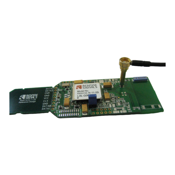
The following diagram illustrates how the user can connect an adapter with Microwave coaxial cable to the switch connector. Figure 2: RF Cable Connected to the RS9110-N-11-03 Evaluation Board : Wi-Fi Data Transfer Tests The evaluation kit allows you to carry out WLAN data transfer tests, where in RS9110-N-11- 03 EVB can be connected to any 802.11abgn Access Points and... -
Page 7: 2: Evaluation Software - Windows Xp
“C:\Program Files\Lite- Fi”. <X_Y_Z> indicates the driver version. For example, LiteFi_2_1_3.exe, means 2. 1.3 version of the W indows XP driver. LiteFi_Driver_Installation_ This is a user guide which provides instructions Guide_WindowsXP.pdf on following topics: Redpine Signals, Inc. Proprietary and Confidential Page 7... -
Page 8: 3: Evaluation Process On Windows Xp
Installation and un-installation of the Wi- Fi driver RS9110_N_11_03_WLAN_T This is a user guide on the usage of the driver est_Procedure_Linux.pdf and wireless configuration utility to do data transfer tests under following categories in Redpine Signals, Inc. Proprietary and Confidential Page 8... -
Page 9: 5: Evaluation Process On Linux
W indows CE platform such as HP- iPAQ PDA: 11g connection – Open System 11g connection with WPA 11n connection with WPA Redpine Signals, Inc. Proprietary and Confidential Page 9... -
Page 10: 7: Evaluation Process On Windows Ce
.7: Evaluation Process on Windows CE You can start the evaluation process as follows: Step 1: - Follow the instructions mentioned in the LiteFi_Driver_Installation_Guide_WindowsCE.pdf Step 2: - Follow the instructions mentioned in the RS9110_N_11_03_WLAN_Test_Procedure_WindowsCE.pdf Redpine Signals, Inc. Proprietary and Confidential Page 10... -
Page 11: 3: Connector Details
C onnector Pin No. Supply J8.1&2 GPIO_1 J8.3 GPIO_0 J8.4 HOST_WAKEUP_INT J8.5 XTAL_IP_EN J8.6 I2C_SCL J8.7 I2C_SDA J8.8 UART1_OUT J8.9 UART1_IN J8.10 W L AN_ACTIVE J8.11 BT_PRIORITY J8.12 UART1_RST J8.13 UART2_OUT J8.14 UART1_CTS J8.15 Redpine Signals, Inc. Proprietary and Confidential Page 11... -
Page 12: Sd Memory Interface
To inherit the modular approval, the antennas for this transmitter must be installed to provide A separation distance of 20cm from all persons and must not be co-located or operating in Conjunction with any other antenna or transmitter. Redpine Signals, Inc. Proprietary and Confidential Redpine Signals, Inc. Proprietary and Confidential Page 12... - Page 13 Manufacturer of the module and the MANUFACTURER OF THE MODULE WILL VERIFY that the product Is incorporated in host equipment in a way that is represented by the testing as shown in the test report. Redpine Signals, Inc. Proprietary and Confidential Page 13...
- Page 14 REMARQUE: Toute modifi cation non autorisée expressément par le fabricant responsable de la onformité peut annuler le droit de l’utilisateur à faire fonctionner le produit. Redpine Signals, Inc. Proprietary and Confidential Page 14...
Need help?
Do you have a question about the RS9110-N-11-03 and is the answer not in the manual?
Questions and answers