Table of Contents
Advertisement
Quick Links
RS9113 Module Evaluation Kit
Redpine Signals, Inc.
2107 N. First Street, #680
Email:
Website:
Redpine Signals, Inc. Proprietary and Confidential
U
s
e
r
G
u
i
d
e
U
s
e
r
G
u
i
d
e
V
e
r
s
i
o
n
2
.
0
V
e
r
s
i
o
n
2
.
0
January 2015
San Jose, CA 95131.
Tel: (408) 748-3385
Fax: (408) 705-2019
info@redpinesignals.com
www.redpinesignals.com
Advertisement
Table of Contents

Related Manuals for Redpine Signals RS9113 EVB


Summary of Contents for Redpine Signals RS9113 EVB
- Page 1 RS9113 Module Evaluation Kit January 2015 Redpine Signals, Inc. 2107 N. First Street, #680 San Jose, CA 95131. Tel: (408) 748-3385 Fax: (408) 705-2019 Email: info@redpinesignals.com Website: www.redpinesignals.com Redpine Signals, Inc. Proprietary and Confidential...
- Page 2 Disclaimer: The information in this document pertains to information related to Redpine Signals, Inc. products. This information is provided as a service to our customers, and may be used for information purposes only. Redpine assumes no liabilities or responsibilities for errors or omissions in this document.
- Page 3 About this Document This document covers the RS9113 Module’s Evaluation Board (EVB) and its usage for evaluating Redpine Signals’ RS9113 based ultra-low-power, single spatial stream, dual-band 802.11n + BT4.0 + ZigBee Convergence modules in n-Link® and WiSeConnect® modes. Redpine Signals, Inc. Proprietary and Confidential...
-
Page 4: Table Of Contents
Access Point Configuration Through AT Commands ...... 50 5.3.4.2 Test Procedure ................ 51 Configuration Over Wi-Fi ............ 52 5.4.1 Configuration to Connect to an Access Point ........52 5.4.2 Configuration to Create an Access Point ........... 58 Redpine Signals, Inc. Proprietary and Confidential Page 4... - Page 5 GPIO Header Pin Description ..........65 7 Appendix B: Using the Bluetooth Manager ......67 8 Appendix C: WiSeConnect® Firmware Upgrade ....70 9 Appendix D: Booting USB Drive on Windows 8 and Later PCs Redpine Signals, Inc. Proprietary and Confidential Page 5...
- Page 6 Table of Figures Figure 1: Evaluation Kit Contents ............... 10 Figure 2: RS9113 EVB ................12 Figure 3: Host SPI Folder Structure ............24 Figure 4: Docklight Startup Dialog Box ............28 Figure 5: Docklight Project Settings Dialog Box ......... 28 Figure 6: Setup for Wi-Fi Client in Personal Security Mode ......
- Page 7 Redpine Signals, Inc. Proprietary and Confidential Page 7...
- Page 8 Table of Tables Table 1: SPI Header Pins ................64 Table 2: SDIO Header Pins ................. 65 Table 3: GPIO Header Pins ................. 66 Redpine Signals, Inc. Proprietary and Confidential Page 8...
-
Page 9: Overview
4) Power Consumption 5) Firmware Upgrade The RS9113 n-Link®, WiSeConnect® module families are based on Redpine Signals' RS9113 ultra-low-power, single spatial stream, dual- band 802.11n + BT4.0 + ZigBee Convergence SoC. The RS9113 module integrates a multi-threaded MAC processor with integrated analog... -
Page 10: Evaluation Kit Contents
OneBox-Mobile driver binaries included for evaluation of n-Link® modules on a standard PC/Laptop platform. The USB drive also has the release package for the Connect-io- n®/WiSeConnect® modules which includes the firmware, documentation and reference projects for multiple platforms. Redpine Signals, Inc. Proprietary and Confidential Page 10... - Page 11 Link® modules and also OS-less MCU platforms for WiSeConnect® modules. The software provided in this kit is to enable easy and quick evaluation on a PC. Please contact Redpine Signals’ Sales (sales@redpinesignals.com) for availability of drivers for an OS and MCU of your choice.
-
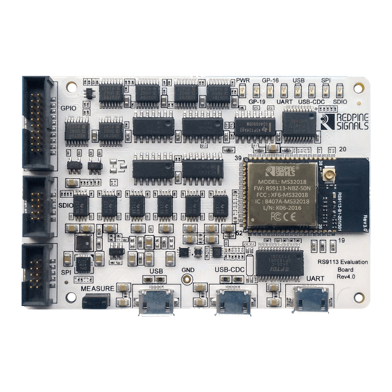
Page 12: Hardware Details
WiSeConnect® modules supports UART, SPI, USB and USB-CDC interfaces to connect to the Host MCU. As shown in the image below, the RS9113 EVB has three USB connectors for the USB, USB-CDC and UART connections. The UART signals of the module are converted to USB using on-board circuit. - Page 13 “MEASURE” on the PCB. The user may connect a power meter or an ammeter to this jumper to measure the current. To proceed further, click on the links below as per your requirement. Evaluation of n-Link® modules Evaluation of WiSeConnect® modules Redpine Signals, Inc. Proprietary and Confidential Page 13...
-
Page 14: Evaluation Of N-Link
The n-Link modules support SDIO and USB as the host interfaces. 4.1 Required Setup RS9113 EVK PC/Laptop to program the RS9113 EVB over SDIO or USB For evaluation of the Wi-Fi Client mode, you will require: Wi-Fi Access Point A second PC/Laptop with Ethernet ... - Page 15 7) Go to the /home/OneBox-Mobile folder and follow the instructions listed in the sub-sections below. 8) To proceed further, click on one of the links below as per your choice. OneBox-Mobile in Wi-Fi Only Mode Redpine Signals, Inc. Proprietary and Confidential Page 15...
-
Page 16: Onebox-Mobile In Wi-Fi Only Mode
For Open (non-Secure) mode network={ ssid=”<SSID of Access Point>” key_mgmt=NONE b. For Open (non-Secure) mode connection to a Hidden SSID network={ ssid=”<SSID of Access Point>” scan_ssid=1 key_mgmt=NONE c. For WEP-64 mode network={ Redpine Signals, Inc. Proprietary and Confidential Page 16... - Page 17 Access Point>” key_mgmt=WPA-PSK psk=<passphrase specified in the Access Point> proto=WPA pairwise=TKIP group=TKIP For WPA2-PSK (CCMP) mode network={ ssid=”<SSID of Access Point>” key_mgmt=WPA-PSK psk=<passphrase specified in the Access Point> proto=WPA2 Redpine Signals, Inc. Proprietary and Confidential Page 17...
-
Page 18: Installation In Access Point Mode
1) Access Point in Open Mode a. Configuration File: wpa_supplicant_open.conf b. This starts an Access Point with the following parameters: i. SSID: REDPINE_AP ii. Channel 1 of 2.4GHz Band (2412 MHz) iii. Open (non-Secure) mode Redpine Signals, Inc. Proprietary and Confidential Page 18... - Page 19 Channel 1 of 2.4GHz Band (2412 MHz) iii. Security Mode: WPA2-PSK (CCMP) iv. Passphrase: “12345678” NOTE: All the above parameters can be modified in the respective configuration files by the user. The values provided are only for reference. Redpine Signals, Inc. Proprietary and Confidential Page 19...
-
Page 20: Installation In Wi-Fi Direct Mode
2) It is recommended that you choose a Wi-Fi channel which has less interference, preferably in the 5GHz band if the EVK is for a Dual band module, to observe optimal throughputs of the module. Redpine Signals, Inc. Proprietary and Confidential Page 20... -
Page 21: Onebox-Mobile In Wi-Fi + Bluetooth Classic Coexistence Mode
This is a one- time process and need not be repeated unless the modules are explicitly removed by the user. 3) Follow the instructions in Section 4.3.1, to install the Wi-Fi Client mode. Redpine Signals, Inc. Proprietary and Confidential Page 21... -
Page 22: Onebox-Mobile In Wi-Fi + Bluetooth Le Coexistence Mode
This is a one- time process and need not be repeated unless the modules are explicitly removed by the user. 3) Follow the instructions in Section 4.3.1, to install the Wi-Fi Client mode. Redpine Signals, Inc. Proprietary and Confidential Page 22... -
Page 23: Onebox-Mobile In Wi-Fi + Zigbee Coexistence Mode
4.3.1, to install the Wi-Fi Client mode. 4) Run the “zigb_insert.sh” script present in the /home/OneBox- Mobile/<interface> folder to start the Zigbee mode. This script inserts Zigbee modules and common HAL modules if not already inserted. Redpine Signals, Inc. Proprietary and Confidential Page 23... -
Page 24: Building And Running The Sample Home Automation Switch Application
The sample application architecture is based on a state machine. Please refer to the app_stateMachine.h file for the defined states and the events. The important sates in the state machine are as follows: Redpine Signals, Inc. Proprietary and Confidential Page 24... -
Page 25: State Callbacks
/home/OneBox-Mobile/<interface> folder. 1) remove_all.sh: Uninstalls the complete driver and all modules, including the common HAL modules. 2) wlan_remove.sh: Uninstalls the Wi-Fi specific modules only. 3) bt_remove.sh: Uninstalls the Bluetooth specific modules only. Redpine Signals, Inc. Proprietary and Confidential Page 25... -
Page 26: Driver Information
You may opt to disable the debug prints of the driver appearing on the console using the command below. Ensure that the driver is installed correctly before using this commad. # echo 0x0 > /proc/onebox-mobile/debug_zone/ Redpine Signals, Inc. Proprietary and Confidential Page 26... -
Page 27: Evaluation Of Connect-Io-N®/Wiseconnect
NOTE: This section describes the evaluation process of the RS9113 modules in Connect-io-n®/WiSeConnect® modes for Wi-Fi using the UART interface. Redpine Signals provides reference projects and APIs for SPI, USB and USB-CDC for Wi-Fi only and also for Coexistence of Wi-Fi with Bluetooth Classic, Bluetooth Low Energy and Zigbee. -
Page 28: Figure 4: Docklight Startup Dialog Box
Figure 5: Docklight Project Settings Dialog Box 7) Select the following options for the Serial port settings: a. Select the COM port in the drop-down menu under “Send/Receive on Comm. Channel”. In the above figure, it is COM8. Redpine Signals, Inc. Proprietary and Confidential Page 28... -
Page 29: Wi-Fi Evaluation In Uart Mode
3) At powerup, the module tries to estimate the baud rate of the Host by exchanging data with it. If no data is sent by the Host, the module defaults to the 115200 bps baud rate in approximately 18 seconds. Redpine Signals, Inc. Proprietary and Confidential Page 29... -
Page 30: Figure 7: Module Startup Messages
SIGNALS”, followed by multiple options. Please see the figure below. Figure 7: Module Startup Messages 4) Hit ‘1’ and press Enter. You will see a message that says, “Loading…” followed by “Loading Done”. Redpine Signals, Inc. Proprietary and Confidential Page 30... -
Page 31: Figure 8: Firmware Loading Messages
This command displays current firmware version in use. e. at+rsi_scan=0 This command scans for available Access Points operating in the 2.4 GHz band. The module responds with information of the Access Points scanned. The data received might have some Redpine Signals, Inc. Proprietary and Confidential Page 31... -
Page 32: Test Procedure
The socket_handle in the response above is used for subsequent commands. 3) Open a TCP client socket on Laptop C by running the TCP.exe application as follows in the Windows Command Prompt: Redpine Signals, Inc. Proprietary and Confidential Page 32... - Page 33 Laptop C. at+rsi_snd=<socket_handle>,<payload_len>,<dest_ipaddr >,<dest_port>,<payload > c. The transmitted data is displayed on the TCP.exe window of Laptop C. 8) The figure below is a snapshot of the TCP.exe application window. Redpine Signals, Inc. Proprietary and Confidential Page 33...
-
Page 34: Wi-Fi Client In Enterprise Security Mode
Figure 10: Setup for Wi-Fi Client in Enterprise Security Mode In the setup shown in the above figure, the WiSeConnect® module on the RS9113 EVB acts as Wi-Fi client. It connects to an Enterprise Security enabled Access Point. The WiSeConnect® module supports four Enterprise Security... -
Page 35: Radius Server Configuration
Radius Server. 4) Open the eap.conf file and make the following changes: a. Change the input for the “default_eap_type” field under the “eap” section to “tls”, as shown in the figure below. Redpine Signals, Inc. Proprietary and Confidential Page 35... -
Page 36: Figure 11: Default Eap Type
Figure 11: Default EAP Type b. Change the inputs for “private_key_file”, “certificate_file” and “CA_file” fields under the “tls” section to “${certsdir}/wifiuser.pem”, as show in the figure below. Redpine Signals, Inc. Proprietary and Confidential Page 36... -
Page 37: Figure 12: Tls Section - I
Figure 12: TLS Section - I c. Uncomment the “fragment_size” and “include_length” lines under the “tls” section, as shown in the figure below. Figure 13: TLS Section – II Redpine Signals, Inc. Proprietary and Confidential Page 37... -
Page 38: Figure 14: Ttls Section
“mschapv2”, as shown in the figure below. Figure 14: TTLS Section 5) Open the users.conf file and add the lines shown in the figure below starting with “user1”. This adds a user with username “user1” and password “test123”. Redpine Signals, Inc. Proprietary and Confidential Page 38... -
Page 39: Access Point Configuration
Access Point pages in a browser by typing the IP address of the Access Point. 2) Navigate to the Wireless Security section and enable the “WPA/WPA2 – Enterprise” option, as shown in the figure below. The page below is for a TP-Link Access Point. Redpine Signals, Inc. Proprietary and Confidential Page 39... -
Page 40: Wi-Fi Client Configuration
Automatic Buad Rate Detection Process for faster bootup. At the end of the timeout, you will see a message like, “WELCOME TO REDPINE SIGNALS”, followed by multiple options. Please see the figure below. Redpine Signals, Inc. Proprietary and Confidential Page 40... -
Page 41: Figure 17: Module Startup Messages
“Loading…” followed by “Loading Done”. Figure 18: Firmware Loading Messages 6) The following commands can now be issued to the module. Please refer to the Software PRM document for detailed description of each Redpine Signals, Inc. Proprietary and Confidential Page 41... - Page 42 Disable Docklight’s serial port connection to the EVB by hitting ‘F6’ when the Docklight window is open. p. Open the Windows Command Prompt and navigate to the RS9113.NBZ.WC.GEN.OSI.x.x.x\utils\Python folder and give the following command: Redpine Signals, Inc. Proprietary and Confidential Page 42...
-
Page 43: Test Procedure
This command opens a Listen TCP socket with port number 5001. 5.3.2.4 Test Procedure 1) Connect Laptop C to the Access Point. It should have proper security credentials to connect to the AP. Redpine Signals, Inc. Proprietary and Confidential Page 43... - Page 44 The module responds to a ping request sent from a remote terminal. There is no command to send a ping request from the module. This is true in all the modes- Client, AP and Wi-Fi Direct. Redpine Signals, Inc. Proprietary and Confidential Page 44...
-
Page 45: Wi-Fi Direct Mode
Wi-Fi Settings of the phone. Figure 19: Android Phone’s Wi-Fi Direct Settings The “Configure Wi-Fi Direct” button can be clicked to set the device name accordingly (Android_phone in this case). Redpine Signals, Inc. Proprietary and Confidential Page 45... - Page 46 The acquired IP address is returned to the Host but might not be readable on the Docklight because of ASCII conversion. You can use the HEX tab of Docklight to see the bytes sent by the module. Redpine Signals, Inc. Proprietary and Confidential Page 46...
- Page 47 DHCP server. The Wi-Fi Direct phone will acquire an IP address from the module automatically (assuming DHCP client is enabled in the phone). Since the Group_Owner_Intent has been set to the lowest value, module will become a Wi-Fi Direct client. Redpine Signals, Inc. Proprietary and Confidential Page 47...
-
Page 48: Figure 20: Command Flow In Wi-Fi Direct Mode
Module associates to the GO. DHCP server of the module. WPA2-PSK is the security mode used. Send at+rsi_ipconf to configure IP of the module. Figure 20: Command Flow in Wi-Fi Direct Mode Redpine Signals, Inc. Proprietary and Confidential Page 48... -
Page 49: Test Procedure
If the remote peer sends data to the module, the module receives it and shows the data in the terminal with the message AT+RSI_READ<ip_version><socket_handle><payload_len><source_ ip_addr><source_port><payload> 5.3.4 Wi-Fi Access Point Mode The figure below shows the setup required for this process. Redpine Signals, Inc. Proprietary and Confidential Page 49... -
Page 50: Access Point Configuration Through At Commands
This is an optional command to report the firmware version in use. e. at+rsi_ipconf=0,192.168.0.30,255.255.255.0,192.168.0. This command configures the IP (192.168.0.30 in this example) of the AP. If this command is not issued, a default IP of 192.168.100.76 will be used. f. at+rsi_apconf=6,redpine,0,0,0,200,3,3 Redpine Signals, Inc. Proprietary and Confidential Page 50... -
Page 51: Test Procedure
Send b. Receive c. Exit 5) Observe that the Docklight on the Wi-Fi AP side (EVB) prints the following message, once the TCP connection is setup with Laptop C. AT+RSI_LTCP_CONNECT=<ip_version><socket_descriptor>,<dest_p ort_no>,<dest_ipaddr><mss><window_size> Redpine Signals, Inc. Proprietary and Confidential Page 51... -
Page 52: Configuration Over Wi-Fi
1. Connect a PC or Host to the module through the USB and power up the module. 1) Configure the module to become an AP by issuing commands from PC (P) as in section Evaluation of Access Point Mode. The sequence of commands is given below. Redpine Signals, Inc. Proprietary and Confidential Page 52... -
Page 53: Figure 22: Module Web Page
3) In the web page that opens, displaying the “Welcome to Redpine Signals” and click on the “GO TO CONFIGURATION PAGE” as shown in below. Figure 22: Module web page Redpine Signals, Inc. Proprietary and Confidential Page 53... - Page 54 IP should be hard coded in the web page. For more details, refer to the section on wireless configuration in the PRM. The module supports iPv6 also. Please refer to the PRM for IPv6 related details. Redpine Signals, Inc. Proprietary and Confidential Page 54...
-
Page 55: Figure 23: Wireless Configuration Page
“at+rsi_cfgenable=0”. Refer to the PRM for more details on these commands. Flow 2: In this flow, the module is connected to an AP. A remote device connects to the same AP and configures the module. Redpine Signals, Inc. Proprietary and Confidential Page 55... -
Page 56: Figure 24: Module Connected To Access Point
SSID: This is the SSID of the AP to which the module should connect after configuration is over. TX POWER: RF power for Tx. Set to ‘2’. CHANNEL: Channel number at which the target AP is present. Set to “11” in this example. Redpine Signals, Inc. Proprietary and Confidential Page 56... -
Page 57: Figure 25: Wireless Configuration Page
The module automatically scans and joins the target AP, after which the stored configuration parameters can be retrieved using the command “at+rsi_cfgget”. If the auto-connect feature needs to be Redpine Signals, Inc. Proprietary and Confidential Page 57... -
Page 58: Configuration To Create An Access Point
Make sure the browser in the laptop does not have any proxies enabled. 4) In the web page that opens, displaying the “Welcome to Redpine Signals” and click on the “GO TO CONFIGURATION PAGE” as shown in below Redpine Signals, Inc. Proprietary and Confidential Page 58... -
Page 59: Figure 27: Module Web Page
BEACON INTERVAL and DTIM COUNT: This to set the beacon parameters of the AP. For example, if beacon interval is 200 (msecs) and DTIM count is 3, the DTIM interval would be 2x300=600 msecs. Redpine Signals, Inc. Proprietary and Confidential Page 59... -
Page 60: Figure 28: Wireless Configuration Page
The stored configuration parameters can be retrieved using the command “at+rsi_cfgget”. If the auto-connect feature needs to be disabled, issue the command “at+rsi_cfgenable=0” to the module. Refer to the PRM for more details on these commands. Redpine Signals, Inc. Proprietary and Confidential Page 60... -
Page 61: Figure 29: Module Connected To Access Point
OPERATING MODE: Access point mode BAND(GHZ): 2.4 SSID: This is the SSID of the AP which will be created after configuration is over TX POWER: RF power for Tx. Set this value to “2”. Redpine Signals, Inc. Proprietary and Confidential Page 61... -
Page 62: Figure 30: Wireless Configuration Page
Click on “SUBMIT” button. The information is sent to the module and stored in its internal flash. 6) The module should now be power cycled or hard reset. It boots up and then automatically creates and AP with the configured Redpine Signals, Inc. Proprietary and Confidential Page 62... - Page 63 The stored configuration parameters can be retrieved using the command “at+rsi_cfgget”. If the auto-connect feature needs to be disabled, issue the command “at+rsi_cfgenable=0” to the module. Refer to the PRM for more details on these commands. Redpine Signals, Inc. Proprietary and Confidential Page 63...
-
Page 64: Appendix A: Headers On The Evb
SPI mode. The interrupt is raised by the EVB to indicate there is data to be read by the Host. RESET Input Active Low Reset to RS9113 module. Table 1: SPI Header Pins Redpine Signals, Inc. Proprietary and Confidential Page 64... -
Page 65: Sdio Header Pin Description
The GPIOs are generally not available for usage from the Host with the standard firmware. Please GPIO_15 refer to the Software PRM for the pins that are GPIO_19 supported or contact Redpine Signals in case you GPIO_16 need to use them. GPIO_7 GPIO_2... - Page 66 Table 3: GPIO Header Pins Redpine Signals, Inc. Proprietary and Confidential Page 66...
-
Page 67: Appendix B: Using The Bluetooth Manager
“Windows” button on the keyboard. You will see Bluetooth symbol at the bottom-right corner of the screen, as show in the image below. Figure 32: Invoking Bluetooth Manager 2) This will open the Bluetooth Manager as shown in the image below. Redpine Signals, Inc. Proprietary and Confidential Page 67... -
Page 68: Figure 33: Bluetooth Manager Basic Window
Figure 33: Bluetooth Manager basic window 3) Click on Search to start inquiry. Figure 34: Click on Search to inquire 4) Select particular device, like your smartphone, right click and select Pair to pair with that device. Redpine Signals, Inc. Proprietary and Confidential Page 68... -
Page 69: Figure 35: Pairing With A Device
“Send a file” to send data to the device. You will be presented with a dialog box to select the file that you wish to send. Figure 36: Send a File to a Device Redpine Signals, Inc. Proprietary and Confidential Page 69... -
Page 70: Appendix C: Wiseconnect® Firmware Upgrade
3) In the Teraterm window, click on Setup -> Terminal… In the dialog box that opens, change the following settings: a. Under “New-line”, select “CR+LF” for Receive and Transmit b. Enable “Local echo”. c. Click OK Redpine Signals, Inc. Proprietary and Confidential Page 70... -
Page 71: Figure 37: Terminal Settings For Teraterm
Serial option and select the COM Port from the drop-down menu. It is COM8 in the figure below. Click OK. 7) After the Automatic Baud Rate Detection timeout, you will see the Welcome message and available options on the Teraterm screen. Redpine Signals, Inc. Proprietary and Confidential Page 71... -
Page 72: Figure 39: Module Startup Messages
8) Hit ‘2’ to select Firmware Upgradation mode. You will be requested to send the Firmware file. For the EVK, the firmware file is present in the USB drive in the RS9113.NBZ.WC.GEN.OSI.x.x.x\Firmware folder. Here, x.x.x is the release version. Redpine Signals, Inc. Proprietary and Confidential Page 72... -
Page 73: Figure 40: Request For Firmware File
9) Click on File -> Transfer -> Kermit -> Send… 10) In the dialog box that opens, navigate to the RS9113.NBZ.WC.GEN.OSI.x.x.x\Firmware folder and select the RS9113.NBZ.WC.GEN.OSI.x.x.x.rps file. 11) A dialog box will open, showing the transfer of the firmware file. Redpine Signals, Inc. Proprietary and Confidential Page 73... -
Page 74: Figure 41: Firmware Transfer Progress
13) You may continue to use the EVB without disconnecting it. If you wish to switch to Docklight from Teraterm, you can click on File -> Disconnect in Teraterm, open Docklight and hit ‘F5’ to start the communication from Docklight. Redpine Signals, Inc. Proprietary and Confidential Page 74... -
Page 75: Appendix D: Booting Usb Drive On Windows 8 And Later Pcs
1) While booting up the PC, press F2 to enter the BIOS setup screen. Figure 42: BIOS Setup Screen 2) Scroll down to the “Security” section on the left part of the screen. You will be shown an option called “Secure Boot”. Redpine Signals, Inc. Proprietary and Confidential Page 75... -
Page 76: Figure 43: Security Screen Of Bios
Figure 43: Security Screen of BIOS 3) Disable the “Secure Boot” option. Figure 44: Disable “Secure Boot” 4) Next, scroll down to the “Advanced” section on the left part of the screen. Redpine Signals, Inc. Proprietary and Confidential Page 76... -
Page 77: Figure 45: Advanced Screen Of Bios
5) Scroll down to the “System Configuration” option under “Advanced” and hit Enter. Figure 46: System Configuration under Advanced 6) In the new screen, you will see an option labeled, “Boot Mode” and it will be in “UEFI Boot” mode. Redpine Signals, Inc. Proprietary and Confidential Page 77... -
Page 78: Figure 47: System Configuration
9) Once these changes are done, the original Windows 8 OS will not be bootable until the changes are reverted. To revert changes, enable UEFI Boot first and then enable Secure Boot (in that order). ***** Redpine Signals, Inc. Proprietary and Confidential Page 78... - Page 79 Revision History Version Date Changes January 2015 Initial Version for Version 2.0 of the EVB Redpine Signals, Inc. Proprietary and Confidential Page 79...
Need help?
Do you have a question about the RS9113 EVB and is the answer not in the manual?
Questions and answers