Table of Contents
Advertisement
Quick Links
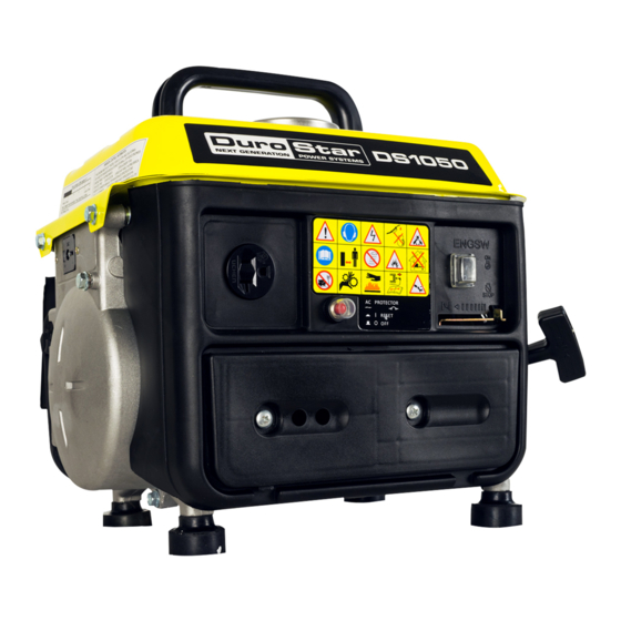
DS1050 GENERATOR
User Manual
REV: DS1050-04022018
5800 Ontario Mills Pkwy
Ontario, CA 91764 USA
This manual provides information regarding the operation
www.duromaxpower.com
and maintenance of these products. We have made every
effort to ensure the accuracy of the information in this
Call our Customer Care Team Toll Free 8-5pm PST Mon-Fri
manual. We reserve the right to change this product at
844-DUROMAX
any time without prior notice.
Advertisement
Table of Contents
Troubleshooting

Subscribe to Our Youtube Channel
Related Manuals for DUROMAX DuroStar DS1050


Summary of Contents for DUROMAX DuroStar DS1050
- Page 1 We have made every effort to ensure the accuracy of the information in this Call our Customer Care Team Toll Free 8-5pm PST Mon-Fri manual. We reserve the right to change this product at 844-DUROMAX any time without prior notice.
-
Page 3: Table Of Contents
CONTENTS Introduction Introduction ........................6 General Safety Procedures .................... 7 Quick Start Guide ......................10 Generator Components ....................12 Package Contents ......................14 Generator Setup Adding Gasoline Mix ..................... 16 Grounding the Generator .................... 17 High Altitude Operation ....................17 Starting the Generator Check the Gas Level ...................... - Page 4 CONTENTS Maintenance and Care Maintenance Schedule ....................32 Maintenance Log ......................33 Cleaning the Air Cleaner ....................34 Spark Plug Maintenance ....................36 Storage and Transportation ..................38 Specifications ......................... 39 Troubleshooting Basic Troubleshooting ....................42 Wiring Diagram ......................43 Warranty .........................
-
Page 6: Introduction
INTRODUCTION DuroMax has cemented its reputation as one of the markets leading power equipment companies who are headquartered in the US. All of our products are manufactured to the strictest guidelines and go through countless testing in all phases of production. -
Page 7: General Safety Procedures
GENERAL SAFETY PROCEDURES SAFETY ALERT SYMBOL The safety alert symbol is used with one of the safety words (DANGER, CAUTION, or WARNING) to alert you of hazards. Please pay attention to these hazard notices both in this manual and on the generator. Please familiarize yourself with the following safety symbols and words: DANGER: Indicates a hazard that will result in serious injury or death if instructions are not ●... - Page 8 GENERAL SAFETY PROCEDURES WARNING: This generator may emit highly flammable and explosive gasoline vapors, which can cause severe burns or even death. A nearby open flame can lead to an explosion even if not directly in contact with gas. Do not operate near an open flame. ●...
- Page 9 GENERAL SAFETY PROCEDURES In addition to the above safety notices, please familiarize yourself with the safety and hazard markings on the generator. Exhuast outlet and muffler will become extremely hot. Do Not Touch.
-
Page 10: Quick Start Guide
QUICK START GUIDE Add gasoline mix The fuel cap is located on top of the fuel tank. Fill the tank with fresh unleaded gasoline 87 octane or higher mixed 50:1 with 2-Stroke Oil. The tank is full when you see fuel in the bottom of the fuel filter cup. - Page 11 Open choke The choke lever is located above the air filter to the left of the recoil start. Slide the lever to the left to open the choke and increase air into the carburetor for normal running. Turn breaker on & connect devices Connect your devices to the receptacles on the front panel.
-
Page 12: Generator Components
GENERATOR COMPONENTS 7. T-Shaped 12VDC 3. Circuit Breaker 4. Engine Switch 6. Ground Terminal 2. Choke Lever 1. Air Cleaner 5. 110V 3-Prong Recepticle 1. Air Cleaner - a removable, cleanable, oiled, sponge-like element that cleans the air going into the engine. - Page 13 8. Fuel Cap 9. Handle 13. Fuel Valve 10. Muffler 11. Spark Plug 12. Recoil Start 8. Fuel Cap - Allows access to fill the fuel tank. 9. Handle - Easy access handle for convenient transportation. 10. Muffler – Reduces engine emissions and reduces nois 11.
-
Page 14: Package Contents
PACKAGE CONTENTS Your generator comes with the items listed below. Please check to see that all of the following items are included with your generator. Spark Plug Wrench Charging Cables Used in spark plug Used to charge Automotive maintenance, inspection, and style 12V Batteries. -
Page 15: Generator Setup
GENERATOR SETUP Proper setup of your generator will get you going as soon as possible while making sure you and your equipment are safe and cared for. -
Page 16: Adding Gasoline Mix
GENERATOR SETUP Step 1 - Adding Gasoline WARNING: Gasoline and gas fumes are highly flammable. Do not fill tank near an open flame. ● Do not overfill. Always check for fuel spills. ● To ensure that the generator runs smoothly use only FRESH, UNLEADED GAS WITH AN OCTANE RATING OF 87 OR HIGHER mixed 50:1 with 2-Stroke Oil. -
Page 17: Grounding The Generator
Step 2 - Grounding the Generator Attach grounding wire Ground the generator by tightening the grounding nut against a grounding wire. Connect the other end to a copper or brass grounding rod that’s driven into the earth. A generally acceptable grounding wire is a No. 12 AWG (American Wire Gauge) stranded copper wire. - Page 19 STARTING THE GENERATOR If this is not your first time using the generator there are still steps you should take to prepare it for operation each time you use it. IMPORTANT: At this point you should be familiar with the procedures described in the first portion of this section entitled “GENERATOR SETUP”...
-
Page 20: Check The Gas Level
STARTING THE GENERATOR Step 1 - Check the gas level Check Gasoline Mix Make sure the generator is on a level surface. Unscrew gas cap and set aside (NOTE: the gas cap may be tight and hard to unscrew). Slowly add unleaded gasoline to the fuel tank. Be careful not to overfill. -
Page 21: Starting The Generator
Starting the Generator Using Gasoline Step 2 - Starting the Generator Turn gas valve on The gas valve is located above the recoil start on the bottom of the fuel tank. Rotate the valve clockwise to the vertical position to turn on the gas supply. Close choke The choke lever is located above the air filter to the right of the recoil start. - Page 22 STARTING THE GENERATOR (CONTINUED) Starting the Generator Using Gasoline Open choke Push the choke to the OPEN position as the engine warms up. CAUTION: Disconnect all electrical loads from the generator before attempting to start!
-
Page 23: Using The Generator
USING THE GENERATOR If this is not your first time using the generator there are still steps you should take to prepare it for operation each time you use it. IMPORTANT: At this point you should be familiar with the procedures described in the first portion of this section entitled “GENERATOR SETUP”... -
Page 24: Ac Usage
USING THE GENERATOR AC Usage ● You may connect electrical devices running on AC current according to their wattage requirements. The chart below shows the rated and surge wattage of your generator according to its model ● number. ● The rated wattage corresponds to the maximum wattage the generator can output on a continuous basis. - Page 25 Tool or Appliance Rated (Running) Watts Additional Surge Watts Electric water heater (40 gal) 1050 Hot plate 2500 Radial arm saw 2000 2000 Electric Stove 1500 Circular Saw 1500 1500 Air compressor (1 HP) 1500 3000 Window air conditioner 1200 1800 Miter saw 1200...
-
Page 26: Connecting A Load To The Generator
USING THE GENERATOR (CONTINUED) Connecting a load to the generator NOTE: Be sure to attach devices to the correct receptacle (outlet). 110v devices can be directly connected to the 110v ONLY receptacles. ● CAUTION: Do not connect 240V loads to the generator. CAUTION: Do not connect 50Hz or 3-phase loads to the generator. - Page 27 Choosing the right power cord Long or thin cords can drain the power provided to an electrical device by the generator. When using such cords, allow for a slightly higher rated wattage requirement for the electrical device. See table below for recommended cords based on the power requirement of the electrical device. DEVICE REQUIREMENTS WIRE GAUGE BY LENGTH (ft.) AMPS...
-
Page 28: Dc Usage
USING THE GENERATOR (CONTINUED) DC Usage CAUTION: The DC receptacle is for recharging 12 Volt automotive-type batteries only. Do not connect any other device to this receptacle. CAUTION: Never try to jump start a car with your generator. Connect the battery Connect one charging wire to the positive terminal on the battery and the other charging wire to the negative terminal on the battery. - Page 29 Charge the battery Allow the generator to run and charge the battery. Charge time may vary based on battery size and age. Disconnecting When disconnecting, always disconnect the wires from the generator first to avoid a spark. DANGER - Stored batteries emit highly explosive hydrogen gas when charged. Batteries also contain acid, which can cause severe chemical burns.
-
Page 31: Maintenance And Care
MAINTENANCE AND CARE Proper maintenance and storage of your generator is essential to ensure trouble free use of your generator when you need it. By following the maintenance and care requirements, you can keep your generator running smooth and efficient for years to come. -
Page 32: Maintenance Schedule
MAINTENANCE AND CARE Proper routine maintenance of your generator is essential for safe, economical, and trouble-free operation. It will also help reduce air pollution. WARNING: Improper maintenance, or failure to correct a problem before operation, can cause a malfunction in which you can be seriously injured or killed. Always follow the inspection and maintenance recommendations and schedules in this instruction manual. -
Page 33: Maintenance Log
MAINTENANCE LOG Date Generator Hours Maintenance Performed... -
Page 34: Cleaning The Air Cleaner
MAINTENANCE AND CARE (CONTINUED) Cleaning the air cleaner Routine maintenance of the air cleaner helps maintain proper airflow to the carburetor. Check that the air cleaner is free of excessive dirt after every use. Note: Improper maintenance may cause less air to enter the engine or dirty air to enter the engine causing overheating and engine wear. - Page 35 Wash cleaner element Wash the sponge-like elements in household dish detergent and warm water. Dry cleaner element Allow the elements to dry completely. Add engine oil to elements Soak the dry elements in a small amount of engine oil. Ring out any excess oil.
-
Page 36: Spark Plug Maintenance
MAINTENANCE AND CARE (CONTINUED) Spark Plug Maintenance The spark plug is important for proper engine operation. A good spark plug should be intact, free of deposits, and properly gapped. Improper maintenance may cause reduced fuel economy, misfires, trouble starting, or damage to the spark plug threads. - Page 37 Measure plug gap Measure the plug gap with a gauge. The gap should be 0.7-0.8 mm (0.028-0.031 in). Clean and re-gap If you are re-using the spark plug, use a wire brush to clean any dirt from around the spark plug base and then re-gap the spark plug.
-
Page 38: Storage And Transportation
MAINTENANCE AND CARE (CONTINUED) Storage and Transportation CAUTION: Never place any type of storage cover on the generator while it is still hot. When transporting your generator: Empty the gas tank (see “Emptying the Gas Tank” in the “Maintenance” section). ●... -
Page 39: Specifications
SPECIFICATIONS AC Rated Wattage (Gasoline) 950W AC Surge Wattage (Gasoline) 1050W AC Rated Voltage 110V AC Rated Frequency 60 Hz AC Phase Single DC Voltage DC Amperage 5.3A Dimensions LENGTH 14in. WIDTH 12in. HEIGHT 13.5in. Engine Type 2-Stroke Forced-Air Ignition System Non-Contact Transistor Displacement 63cc... -
Page 41: Troubleshooting
TROUBLESHOOTING This section of the manual is to help you troubleshoot problems with your generator. -
Page 42: Basic Troubleshooting
TROUBLESHOOTING Mode Description Engine Switch is “Off” Set engine switch to “run” Fuel Valve is “Closed” Turn fuel valve to “open” Choke is open Close the choke Engine is out of fuel Add fuel Engine will not start Fuel is old or contaminated Change fuel Spark Plug is dirty Clean spark plug... -
Page 43: Wiring Diagram
WIRING DIAGRAM... -
Page 44: Warranty
Warranty Limitations DuroMax/DuroStar Power Equipment does not claim or hold any obligation to loss of time, freight charges, use of product, or any incidental damages from the use of this product. THIS WARRANTY IS IN LIEU OF ALL OTHER WARRANTIES, EXPRESSED OR IMPLIED. - Page 45 Equipment cannot deny warranty solely for the lack of receipts or your failure to ensure the performance of all scheduled maintenance. As the small off-road engine owner, you should however be aware that the DuroMax Power ● Equipment may deny you warranty coverage if your small off-road engine or a part has failed due to abuse, neglect, or improper maintenance or unapproved modifications.
- Page 46 WARRANTY (CONTINUED) 1. Any warranted part that is scheduled only for regular inspection in the Owner’s Manual must be warranted for the warranty period stated above. A statement in such written instructions to the effect of “repair or replace as necessary” will not reduce the period of warranty coverage. Any such part repaired or replaced under warranty must be warranted for the remaining warranty period.
- Page 47 Exhaust Emission Warranty Parts List. Hoses, belts, connectors, and assemblies. Fuel Metering System Evaporative Emission Warranty Part List Carburetor and internal parts (and/or Fuel Tank* pressure regulator or fuel injection Fuel Cap system). iii. Fuel Line Fuel Line Fittings Air/fuel ratio feedback and control Clamps** system.
-
Page 48: Contact Information
CUSTOMER SERVICE Duromax Power Equipment is comitted to ensuring that our products perform when they need to. Our generators are your lifeline in the event of an emergency. Should you have any problems, please contact our customer service department: DUROMAX POWER EQUIPMENT... - Page 50 5800 Ontario Mills Parkway Ontario, CA 91764 United States 844-DUROMAX...
Need help?
Do you have a question about the DuroStar DS1050 and is the answer not in the manual?
Questions and answers