Table of Contents
Advertisement
Quick Links
To the Installer:
Please attach these instructions
next to the water heater.
Installation and Operation Instructions Manual
WARNING: If the information in these instructions is not followed exactly, a
fire or explosion may result causing property damage, personal injury or death.
– Do not store or use gasoline or other flammable
vapors and liquids in the vicinity of this or any
other appliance.
– WHAT TO DO IF YOU SMELL GAS
• Do not try to light any appliance.
• Do not touch any electrical switch; do not use
any phone in your building.
WARNING
Improper installation, adjustment, alteration,
service or maintenance can cause serious injury
or property damage. Refer to this manual. For
assistance or additional information, consult a
qualified installer or service agency.
WARNING
Install in accordance with all local codes. In the
absence of local codes, refer to NFPA 54 or CSA
B149.1.
CAUTION
The recommended temperature for normal
residential use is 120°F. The dial on the aquastat
does not always reflect the out-coming water
temperature and it could occasionally exceed
120°F. Variation in out-coming temperature could
be based on factors including but not limited to
usage patterns and type of installation.
WARNING
Hotter water increases the risk of scald injury.
Before adjusting the water temperature setting,
read this instruction manual. Temperatures at
which injury occurs vary with the person's age
and the length of exposure. The slower reaction
time of children, elderly or physically or mentally
challenged persons increases the scalding hazard
to them. It is recommended that lower water
temperatures be used where these exposure hazards
exist. Households with small children or invalids
may require a temperature setting less than 120°F
to prevent accidental contact with hot water.
To produce less than 120°F, use point-of-use
temperature limiting devices.
23435 EN
To the Consumer:
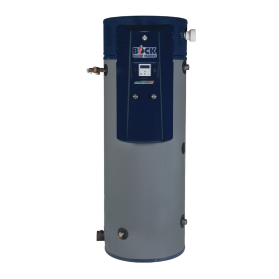
High Efficiency Commercial Gas Water Heater
Models: OT200, OT250, OT299
Warranty, Registration Card and Parts List are included.
Owner: Please remember to return the Registration Card!
– Installation and service must be performed by a
Please read these and all component
instructions and keep for future reference.
• Immediately call your gas supplier from a neigh-
bor's phone. Follow the gas supplier's instructions.
• If you cannot reach your gas supplier, call the fire
department.
qualified installer, service agency or the gas supplier.
If higher water temperature is needed in part of
the water system, automatic temperature limiting
devices must be used on all lines to water taps.
WARNING
Water heater blankets may restrict air flow to the
water heater and cause fire, asphyxiation, personal
injury or death.
THIS MANUAL HAS BEEN PREPARED TO
ACQUAINT YOU WITH THE INSTALLATION,
OPERATION, AND MAINTENANCE OF YOUR
WATER HEATER AND TO PROVIDE IMPORTANT
SAFETY INFORMATION.
Read all instructions thoroughly before attempting
installation or operation of your water heater. Keep
these instructions for future reference.
Local plumbing and electrical codes must be
followed in the installation of this water heater.
In the absence of a local code use the UNIFORM
PLUMBING CODE and the NFPA Code. Local codes
may supersede instructions in this installation
manual.
These instructions are a guide for the correct
installation of the water heater. The manufacturer
will not be liable for damages caused by failure to
comply with the installation and operating instruc-
tions outlined on the following pages.
DO NOT use this appliance if any part has been
under water. Immediately call a qualified service
technician to inspect the appliance and to replace
any part of the control system and any gas control
which has been under water.
FAILURE TO FOLLOW THESE INSTRUCTIONS OR
ALL APPLICABLE BUILDING CODES
AND REGULATIONS VOIDS THE WARRANTY ON
THIS WATER HEATER.
Rev4 4/21
Advertisement
Table of Contents


Need help?
Do you have a question about the OT200 and is the answer not in the manual?
Questions and answers