Table of Contents
Advertisement
Quick Links
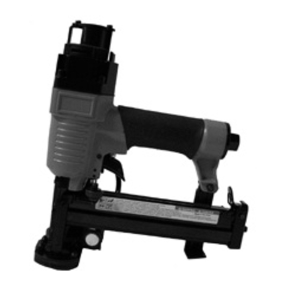
PLASTIC CAP STAPLER
SET UP AND OPERATING INSTRUCTIONS
Visit our website at: http://www.harborfreight.com
Read this material before using this product.
Failure to do so can result in serious injury.
SAVE THIS MANUAL.
©
Copyright
2008 by Harbor Freight Tools
contained herein may be reproduced in any shape or form without the express written consent of
Harbor Freight Tools. Diagrams within this manual may not be drawn proportionally. Due to continuing
improvements, actual product may differ slightly from the product described herein. Tools required for
assembly and service may not be included.
For technical questions or replacement parts, please call 1-800-444-3353.
Revised Manual 10f
99637
®
. All rights reserved. No portion of this manual or any artwork
Advertisement
Table of Contents

Related Manuals for Central Pneumatic PLASTIC CAP STAPLER 99637


Summary of Contents for Central Pneumatic PLASTIC CAP STAPLER 99637
- Page 1 PLASTIC CAP STAPLER SET UP AND OPERATING INSTRUCTIONS Visit our website at: http://www.harborfreight.com Read this material before using this product. Failure to do so can result in serious injury. SAVE THIS MANUAL. © Copyright 2008 by Harbor Freight Tools contained herein may be reproduced in any shape or form without the express written consent of Harbor Freight Tools.
-
Page 2: Important Safety Instructions
SAVE THIS MANUAL Keep this manual for the safety warn- ings and precautions, assembly, operating, inspection, maintenance and cleaning pro- cedures. Write the product’s serial number in the back of the manual (or month and year of purchase if product has no num- ber). -
Page 3: Personal Safety
Stapler. Distractions are able to re- sult in the loss of control of the tool. Personal safety Stay alert. Watch what you are do- ing and use common sense when operating the tool. Do not use the tool while tired or under the influ- ence of drugs, alcohol, or medica- tion. -
Page 4: Air Source
Do not use the Stapler if the Trig- ger (39) does not turn the tool on or off. Any tool that cannot be con- trolled with the Trigger is dangerous and must be repaired. Disconnect the Stapler from the air source before making any adjust- ments, changing accessories, or storing the tool. -
Page 5: Symbols And Specific Safety Instructions
SYMBOLS AND SPECIFIC SAFETY INSTRUCTIONS Symbol Definitions Symbol Property or statement No-load speed Revolutions or reciprocation per .../min minute Pounds per square inch of pressure ft-lb Foot-pounds of torque Blows per minute Cubic Feet per Minute flow Cubic Feet per Minute flow at SCFM standard conditions National pipe thread, tapered... - Page 6 Obey the manual for the air compres- sor used to power this Stapler. Install an in-line shutoff valve to allow immediate control over the air supply in an emergency, even if a hose is ruptured. Use this Stapler with both hands only. Using tools with only one hand can result in loss of control.
-
Page 7: Product Specifications
PRODUCT SPECIFICATIONS Air Pressure Range 70-90 PSI Air Hose Requirement 3/8” I.D. Air Inlet 1/4” -18 NPT Air Consumption 6.0 CFM Fastener Type Staples with Plastic Caps Staple Length 3/8” to 1-1/4” Staple Crown Size 3/8” Crown Staple Gauge 18 Gauge Plastic Cap Diameter 1”... - Page 8 Incorporate a filter, regulator, oiler and shut off valve for best service, as shown in the diagram above. An in- line shutoff valve is an important safety device because it can imme- diately shut-off air flow in case of tool or hose failure. Note: If an automatic oiler system is not used, add a few drops of Pneumatic Tool Oil to the airline connection be-...
- Page 9 discharge the tool in a safe fashion after disconnecting to ensure that the tool is disconnected and unpowered. OPERATING INSTRUCTIONS Read the ENTIRE IMPORTANT SAFETY INFORMATION section at the beginning of this manual including all text under subheadings therein before set up or use of this product.
- Page 10 FIGURE C (MAGAZINE OPENED) MAGAZINE FIGURE D (MAGAZINE CLOSED) To load plastic caps into the Cap Canister (105), insert the plastic caps into the Cap Canister. Turn the Canister Latch (104) to apply pres- sure on the caps. Then remove the cap holder line from the plastic caps.
-
Page 11: Work Area Set Up
only once. With the Trigger held, carefully lift the Stapler and press it against the scrap wood again. The tool must not cycle (fire). If it fails to perform in the manner explained in bold, have it repaired by a quali- fied service technician. -
Page 12: Maintenance Instructions
depressed, gently and briefly squeeze the Trigger (39) once. One staple and plastic cap will be fired. Do not press the Bottom Plate (95) against the workpiece with excessive force. Allow the tool to do the work. Always allow the tool to recoil off the work surface. -
Page 13: Please Read The Following Carefully
filter must be regularly drained. Per- forming routine maintenance on the air supply will allow the tool to oper- ate more safely and will also reduce wear on the tool. After each use: • Clean the exterior of the Stapler us- ing a clean cloth. -
Page 14: Troubleshooting
Problem Possible Causes Decreased output. 1. Not enough air pressure and/ or air flow. 2. Obstructed trigger. 3. Incorrect lubrication or not enough lubrication. 4. Blocked air inlet screen (if equipped). 5. Air leaking from loose housing. 6. Mechanism contaminated. 1. -
Page 15: Parts List
Part # Description Exhaust Cap Hex Bolt Spring Washer Cylinder Cap Unit Seal Internal Lining O-Ring Compression Spring Gasket (Cylinder Cap) O-Ring Head Valve/Piston Valve O-Ring O-Ring O-Ring Collar O-Ring Piston Up Cover & Driver O-Ring Lining Ring Cylinder O-Ring O-Ring Bumper Air Plug... - Page 16 PARTS LIST - CONTINUED Part # Description Driver Guide Connecting Plate Hex Bolt Spring Plate Spring Plate Retainer Ring Fixing Seat Cylinder Bushing O-Ring Piston Spring Stopper Retainer Ring Driver Blade Pusher Cylinder Shelter Plate SKU 99637 For technical questions, please call 1-800-444-3353. Part # Description Plate...
-
Page 17: Assembly Diagram
ASSEMBLY DIAGRAM SKU 99637 For technical questions, please call 1-800-444-3353. Page 17... - Page 18 90 Day Warranty Harbor Freight Tools Co. makes every effort to assure that its products meet high quality and durability standards, and warrants to the original purchaser that this product is free from defects in materials and workmanship for the period of 90 days from the date of purchase.
Need help?
Do you have a question about the PLASTIC CAP STAPLER 99637 and is the answer not in the manual?
Questions and answers