Table of Contents
Advertisement
Quick Links
Advertisement
Table of Contents

Subscribe to Our Youtube Channel
Related Manuals for Comtrend Corporation WR-6891u


Summary of Contents for Comtrend Corporation WR-6891u
- Page 1 WR-6891u FTTH Gateway User Manual 261097-018 Version A1.0, May 28, 2015...
- Page 2 Preface This manual provides information related to the installation and operation of this device. The individual reading this manual is presumed to have a basic understanding of telecommunications terminology and concepts. If you find the product to be inoperable or malfunctioning, please contact technical support for immediate service by email at INT-support@comtrend.com For product update, new product release, manual revision, or software upgrades,...
- Page 3 Copyright Copyright©2015 Comtrend Corporation. All rights reserved. The information contained herein is proprietary to Comtrend Corporation. No part of this document may be translated, transcribed, reproduced, in any form, or by any means without prior written consent of Comtrend Corporation.
-
Page 4: Table Of Contents
Table of Contents CHAPTER 1 INTRODUCTION ......................6 1.1 A ........................... 7 PPLICATION CHAPTER 2 INSTALLATION ......................8 2.1 H ........................... 8 ARDWARE ETUP 2.2 LED I .......................... 10 NDICATORS CHAPTER 3 WEB USER INTERFACE .................... 12 ... - Page 5 6.2 S ............................67 ECURITY 6.2.1 IP Filtering ........................67 6.2.2 MAC Filtering......................... 70 6.3 Q S) ......................72 UALITY OF ERVICE 6.3.1 QoS Queue Setup ......................73 6.3.2 QoS Policer ........................75 ...
- Page 6 APPENDIX E - CONNECTION SETUP ..................133 APPENDIX F - WPS OPERATION ....................149 APPENDIX G - PRINTER SERVER ....................154...
-
Page 7: Chapter 1 Introduction
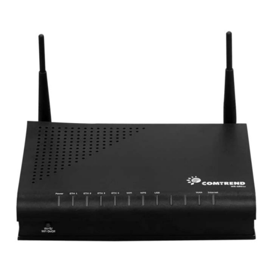
Chapter 1 Introduction The WR-6891u is an 802.11n 2.4GHz concurrently compliant VoIP Gateway. It employs a 10/100/1000 Base-T Gigabit Ethernet port for WAN, four 10/100/1000 Base-T Gigabit Ethernet ports for LAN, one USB Host, one WiFi On-Off/WPS button, and an integrated 802.11n 2.4GHz(2T2R) for WLAN Access Point (AP), which is backward... -
Page 8: Application
1.1 Application The following diagram depicts the application of the WR-6891u with GPON. -
Page 9: Chapter 2 Installation
2.2 LED Indicators). NOTE: If pressed down for more than 20 seconds, the WR-6891u will go into a firmware update state (CFE boot mode). The firmware can then be updated using an Internet browser pointed to the default IP address. - Page 10 FRONT PANEL WPS/WLAN Switch Press the WPS/WIFI button for 5 seconds to enable the WIFI function (then WIFI led should light up). Press for another 5 seconds to enable WPS which will allow 5 minutes for WIFI connection. To disable WIFI, press the WPS/WIFI button for 10 seconds and then WLAN led should go off.
-
Page 11: Led Indicators
2.2 LED Indicators The front panel LED indicators are shown below and explained in the following table. This information can be used to check the status of the device and its connections. Color Mode Function The device is powered up. GREEN The device is powered down. - Page 12 An Ethernet WAN Link is established. An Ethernet WAN Link is not GREEN established. Data transmitting or receiving over Ethernet WAN. IP connected and no traffic detected. If an IP or PPPoE session is dropped due to an idle timeout, the light will remain green if an ADSL connection is still present.
-
Page 13: Chapter 3 Web User Interface
3.2 IP Configuration DHCP MODE When the WR-6891u powers up, the onboard DHCP server will switch on. Basically, the DHCP server issues and reserves IP addresses for LAN devices, such as your PC. To obtain an IP address from the DCHP server, follow the steps provided below. - Page 14 STEP 4: Click OK to submit these settings. If you experience difficulty with DHCP mode, you can try static IP mode instead. STATIC IP MODE In static IP mode, you assign IP settings to your PC manually. Follow these steps to configure your PC IP address to use subnet 192.168.1.x. NOTE: The following procedure assumes you are running Windows XP.
- Page 15 STEP 4: Click OK to submit these settings.
-
Page 16: Login Procedure
3.3 Login Procedure Perform the following steps to login to the web user interface. NOTE: The default settings can be found in Section 3.1. STEP 1: Start the Internet browser and enter the default IP address for the device in the Web address field. For example, if the default IP address is 192.168.1.1, type http://192.168.1.1. - Page 17 You can also reach this page by clicking on the following icon located at the top of the screen.
-
Page 18: Chapter 4 Device Information
Chapter 4 Device Information You can reach this page by clicking on the following icon located at the top of the screen. The web user interface window is divided into two frames, the main menu (at left) and the display screen (on the right). The main menu has several options and selecting each of these options opens a submenu with more selections. -
Page 19: Wan
4.1 WAN Select WAN from the Device Info submenu to display the configured PVC(s). Heading Description Interface Name of the interface for WAN Description Name of the WAN connection Type Shows the connection type VlanMuxId Shows 802.1Q VLAN ID IPv6 Shows WAN IPv6 status IGMP Shows Internet Group Management Protocol (IGMP) -
Page 20: Statistics
4.2 Statistics This selection provides LAN, WAN, ATM and xDSL statistics. NOTE: These screens are updated automatically every 15 seconds. Click Reset Statistics to perform a manual update. 4.2.1 LAN Statistics This screen shows data traffic statistics for each LAN interface. Heading Description Interface... -
Page 21: Wan Service
4.2.2 WAN Service This screen shows data traffic statistics for each WAN interface. Heading Description Interface WAN interfaces Description WAN service label Received/Transmitted - Bytes Number of Bytes - Pkts Number of Packets - Errs Number of packets with errors - Drops Number of dropped packets... -
Page 22: Route
4.3 Route Choose Route to display the routes that the WR-6891u has found. Field Description Destination Destination network or destination host Gateway Next hop IP address Subnet Mask Subnet Mask of Destination Flag U: route is up !: reject route... -
Page 23: Arp
4.4 ARP Click ARP to display the ARP information. Field Description IP address Shows IP address of host pc Flags Complete, Incomplete, Permanent, or Publish HW Address Shows the MAC address of host pc Device Shows the connection interface 4.5 DHCP Click DHCP to display all DHCP Leases. - Page 24 Field Description IPv6 Address Shows IP address of device/host/PC MAC Address Shows the Ethernet MAC address of the device/host/PC Duration Shows leased time in hours Expires In Shows how much time is left for each DHCP Lease...
-
Page 25: Nat Session
4.6 NAT Session Click the “Show All” button to display the following. Field Description Source IP The source IP from which the NAT session is established Source Port The source port from which the NAT session is established Destination IP The IP which the NAT session was connected to Destination Port The port which the NAT session was connected to... -
Page 26: Igmp Proxy
4.7 IGMP Proxy Field Description Interface The Source interface from which the IGMP report was received The WAN interface from which the multicast traffic is received Groups The destination IGMP group address Member The Source IP from which the IGMP report was received Timeout The time remaining before the IGMP report expires... -
Page 27: Ipv6
4.8 IPv6 4.8.1 IPv6 Info Field Description Interface WAN interface with IPv6 enabled Status Connection status of the WAN interface Address IPv6 Address of the WAN interface Prefix Prefix received/configured on the WAN interface Device Link-local Address The CPE's LAN Address Default IPv6 Gateway The default WAN IPv6 gateway IPv6 DNS Server... -
Page 28: Ipv6 Neighbor
4.8.2 IPv6 Neighbor Field Description IPv6 Address Ipv6 address of the device(s) found Flags Status of the neighbor device HW Address MAC address of the neighbor device Device Interface from which the device is located... -
Page 29: Ipv6 Route
4.8.3 IPv6 Route Field Description Destination Destination IP Address Gateway Gateway address used for destination IP Metric Metric specified for gateway Interface Interface used for destination IP... -
Page 30: Network Map
4.9 Network Map The network map is a graphical representation of router’s wan status and LAN devices. The feature is only available using a non-IE browser. -
Page 31: Wireless
4.10 Wireless 4.10.1 Station Info This page shows authenticated wireless stations and their status. Click the Refresh button to update the list of stations in the WLAN. Consult the table below for descriptions of each column heading. Field Description Lists the MAC address of all the stations. Associated Lists all the stations that are associated with the Access Point, along with the amount of time since packets were... -
Page 32: Site Survey
4.10.2 Site Survey The graph displays wireless APs found in your neighborhood by channel. -
Page 33: Chapter 5 Basic Setup
Chapter 5 Basic Setup You can reach this page by clicking on the following icon located at the top of the screen. This will bring you to the following screen. -
Page 34: Wan Setup
5.1 Wan Setup Add or remove ETH WAN interface connections here. Click Add to create a new Layer 2 Interface (see Appendix E - Connection Setup). To remove a connection, click the Remove button. -
Page 35: Wan Service Setup
5.1.1 WAN Service Setup This screen allows for the configuration of WAN interfaces. Click the Add button to create a new connection. For connections on ATM or PTM or ETH WAN interfaces see Appendix E - Connection Setup. To remove a connection, select its remove checkbox and click Remove. Heading Description Interface... -
Page 36: Nat
5.2 NAT To display this option, NAT must be enabled in at least one PVC. NAT is not an available option in Bridge mode. 5.2.1 Virtual Servers Virtual Servers allow you to direct incoming traffic from the WAN side (identified by Protocol and External port) to the internal server with private IP addresses on the LAN side. - Page 37 Consult the table below for field and header descriptions. Field/Header Description Choose All Interface Virtual server rules will be created for all WAN interfaces. Choose One Interface Select a WAN interface from the drop-down menu. Use Interface Select a Service User should select the service from the list.
- Page 38 Field/Header Description Internal Port End Enter the internal port ending number (when you select Custom Server). When a service is selected, the port ranges are automatically configured.
-
Page 39: Port Triggering
5.2.2 Port Triggering Some applications require that specific ports in the firewall be opened for access by the remote parties. Port Triggers dynamically 'Open Ports' in the firewall when an application on the LAN initiates a TCP/UDP connection to a remote party using the 'Triggering Ports'. - Page 40 Consult the table below for field and header descriptions. Field/Header Description Use Interface Select a WAN interface from the drop-down menu. Select an Application User should select the application from the list. Custom Application User can enter the name of their choice. Trigger Port Start Enter the starting trigger port number (when you select custom application).
-
Page 41: Dmz Host
5.2.3 DMZ Host The DSL router will forward IP packets from the WAN that do not belong to any of the applications configured in the Virtual Servers table to the DMZ host computer. To Activate the DMZ host, enter the DMZ host IP address and click Save/Apply. To Deactivate the DMZ host, clear the IP address field and click Save/Apply. -
Page 42: Ip Address Map
5.2.4 IP Address Map Mapping Local IP (LAN IP) to some specified Public IP (WAN IP). Field/Header Description Rule The number of the rule Type Mapping type from local to public. Local Start IP The beginning of the local IP Local End IP The ending of the local IP Public Start IP... - Page 43 One to One: mapping one local IP to a specific public IP Many to one: mapping a range of local IP to a specific public IP Many to many(Overload): mapping a range of local IP to a different range of public IP Many to many(No Overload): mapping a range of local IP to a same range of public IP...
-
Page 44: Ipsec Alg
5.2.5 IPSEC ALG IPSEC ALG provides multiple VPN passthrough connection support, allowing different clients on LAN side to establish a secured IP Connection to the W AN server. To enable IPSEC ALG, tick the checkbox and click the Save button. -
Page 45: Sip Alg
5.2.6 SIP ALG This page allows you to enable / disable SIP ALG. -
Page 46: Lan
5.3 LAN Configure the LAN interface settings and then click Apply/Save. Consult the field descriptions below for more details. GroupName: Select an Interface Group. LAN INTERFACE IP Address: Enter the IP address for the LAN port. Subnet Mask: Enter the subnet mask for the LAN port. IGMP Snooping: Standard Mode: In standard mode, multicast traffic will flood to all bridge ports when no client subscribes to a multicast... - Page 47 Blocking Mode: In blocking mode, the multicast data traffic will be blocked and not flood to all bridge ports when there are no client subscriptions to any multicast group. Enable Enhanced IGMP: Enable by ticking the checkbox . IGMP packets between LAN ports will be blocked.
- Page 48 LAN INTERFACE To configure a secondary IP address, tick the checkbox outlined (in RED) below. IP Address: Enter the secondary IP address for the LAN port. Subnet Mask: Enter the secondary subnet mask for the LAN port. Ethernet Media Type: Configure auto negotiation, or enforce selected speed and duplex mode for the Ethernet ports.
-
Page 49: Lan Ipv6 Autoconfig
5.3.1 LAN IPv6 Autoconfig Configure the LAN interface settings and then click Save/Apply. Consult the field descriptions below for more details. LAN IPv6 Link-Local Address Configuration Heading Description EUI-64 Use EUI-64 algorithm to calculate link-local address from MAC address User Setting Use the Interface Identifier field to define a link-local address... - Page 50 Static LAN IPv6 Address Configuration Heading Description Interface Address Configure static LAN IPv6 address and subnet prefix (prefix length is length required): IPv6 LAN Applications Heading Description Stateless Use stateless configuration Refresh Time (sec): The information refresh time option specifies how long a client should wait before refreshing information retrieved from DHCPv6 Stateful...
- Page 51 Heading Description Enable RADVD Enable use of router advertisement daemon RA interval Min(sec): Minimum time to send router advertisement RA interval Max(sec): Maximum time to send router advertisement Reachable Time(ms): The time, in milliseconds that a neighbor is reachable after receiving reachability confirmation Default Preference: Preference level associated with the default...
-
Page 52: Static Ip Neighbor
5.3.2 Static IP Neighbor Click the Add button to display the following. Click Apply/Save to apply and save the settings. Heading Description IP Version The IP version used for the neighbor device IP Address Define the IP Address for the neighbor device MAC Address The MAC Address of the neighbor device Associated Interface... -
Page 53: Upnp
5.3.3 UPnP Select the checkbox provided and click Apply/Save to enable UPnP protocol. -
Page 54: Wireless
5.4 Wireless 5.4.1 Basic The Basic option allows you to configure basic features of the wireless LAN interface. Among other things, you can enable or disable the wireless LAN interface, hide the network from active scans, set the wireless network name (also known as SSID) and restrict the channel set based on country requirements. - Page 55 Option Description Hide Access Select Hide Access Point to protect the access point from detection by Point wireless active scans. To check AP status in Windows XP, open Network Connections from the start Menu and select View Available Network Connections. If the access point is hidden, it will not be listed there.
-
Page 56: Security
5.4.2 Security The following screen appears when Wireless Security is selected. The options shown here allow you to configure security features of the wireless LAN interface. Please see 6.10.3 WPS for WPS setup instructions. Click Apply/Save to implement new configuration settings. WIRELESS SECURITY Setup requires that the user configure these settings using the Web User Interface (see the table below). - Page 57 The settings for WPA authentication are shown below. The settings for WPA2-PSK authentication are shown next.
- Page 58 WEP Encryption This option specifies whether data sent over the network is encrypted. The same network key is used for data encryption and network authentication. Four network keys can be defined although only one can be used at any one time. Use the Current Network Key list box to select the appropriate network key.
-
Page 59: Parental Control
5.5 Parental Control This selection provides WAN access control functionality. 5.5.1 Time Restriction This feature restricts access from a LAN device to an outside network through the device on selected days at certain times. Make sure to activate the Internet Time server synchronization as described in section 8.5 Internet Time, so that the... -
Page 60: Url Filter
5.5.2 URL Filter This screen allows for the creation of a filter rule for access rights to websites based on their URL address and port number. Select URL List Type: Exclude or Include. Tick the Exclude radio button to deny access to the websites listed. Tick the Include radio button to restrict access to only those listed websites. - Page 61 A maximum of 100 entries can be added to the URL Filter list.
-
Page 62: Home Networking
5.6 Home networking 5.6.1 Print Server This page allows you to enable or disable printer support. Please reference Appendix G to see the procedure for enabling the Printer Server. 5.6.2 DLNA Enabling DLNA allows users to share digital media, like pictures, music and video, to other LAN devices from the digital media server. -
Page 63: Storage Service
5.6.3 Storage Service Enabling Samba service allows the user to share files on the storage device. Different levels of user acce ss can be configured after samba security mode is enabled. This page also displays storage devices attached to USB host. Display after storage device attached (for your reference). -
Page 64: Chapter 6 Advanced Setup
Chapter 6 Advanced Setup You can reach this page by clicking on the following icon located at the top of the screen. 6.1 Auto-detection setup The auto-detection function is used for CPE to detect WAN service for either ETHWAN or xDSL interface. The feature is designed for the scenario that requires only one WAN service in different applications. - Page 65 Enter the PPP username/password given by your service provider for PPP service detection. Select a LAN-as-WAN Ethernet port for auto-detect: Select the Ethernet Port that will be used as ETHWAN during auto-detection.
- Page 66 WAN services list: A maximum of 7 W AN services with corresponding VLAN ID (-1 indicates no VLAN ID is required for the service) are required to be configured for ETHWAN. The services will be detected in order. Users can modify the 7 pre-configured services and select disable to ignore any of the services to meet their own requirements.
- Page 67 Auto Detection notice Note: The following description concerning ETHWAN is for multiple LAN port devices only. 1) This feature will automatically detect one WAN service only. If customers require multiple WAN services, manual configuration is required. 2) If a physical ETHWAN port is detected, the Auto Detection for ETHWAN will be fixed on the physical ETHWAN port and cannot be configured for any LAN port;...
-
Page 68: Security
6.2 Security To display this function, you must enable the firewall feature in WAN Setup. For detailed descriptions, with examples, please consult Appendix A - Firewall. 6.2.1 IP Filtering This screen sets filter rules that limit IP traffic (Outgoing/Incoming). Multiple filter rules can be set and each applies at least one limiting condition. - Page 69 Consult the table below for field descriptions. Field Description Filter Name The filter rule label IP Version Select from the drop down menu. Protocol TCP, TCP/UDP, UDP, or ICMP. Source IP address Enter source IP address. Source Port (port or port:port) Enter source port number or range.
- Page 70 Consult the table below for field descriptions. Field Description Filter Name The filter rule label. IP Version Select from the drop down menu. Protocol TCP, TCP/UDP, UDP, or ICMP. Policy Permit/Drop packets specified by the firewall rule. Source IP address Enter source IP address.
-
Page 71: Mac Filtering
Each network device has a unique 48-bit MAC address. This can be used to filter (block or forward) packets based on the originating device. MAC filtering policy and rules for the WR-6891u can be set according to the following procedure. The MAC Filtering Global Policy is defined as follows. FORWARDED means that all MAC layer frames will be FORWARDED except those matching the MAC filter rules. - Page 72 Click Save/Apply to save and activate the filter rule. Consult the table below for detailed field descriptions. Field Description Protocol Type PPPoE, IPv4, IPv6, AppleTalk, IPX, NetBEUI, IGMP Destination MAC Address Defines the destination MAC address Source MAC Address Defines the source MAC address Frame Direction Select the incoming/outgoing packet interface WAN Interfaces...
-
Page 73: Quality Of Service (Qos)
6.3 Quality of Service (QoS) NOTE: QoS must be enabled in at least one PVC to display this option. (see Appendix E - Connection Setup for detailed PVC setup instructions). To Enable QoS tick the checkbox and select a Default DSCP Mark. Click Apply/Save to activate QoS. -
Page 74: Qos Queue Setup
6.3.1 QoS Queue Setup Configure queues with different priorities to be used for QoS setup. In ATM mode, maximum 16 queues can be configured. In PTM mode, maximum 8 queues can be configured. For each Ethernet interface, maximum 3 queues can be configured. To add a queue, click the Add button. - Page 75 Click Add to display the following screen. Name: Identifier for this Queue entry. Enable: Enable/Disable the Queue entry. Interface: Assign the entry to a specific network interface (QoS enabled). After selecting an Interface the following will be displayed. The precedence list shows the scheduler algorithm for each precedence level. Queues of equal precedence will be scheduled based on the algorithm.
-
Page 76: Qos Policer
6.3.2 QoS Policer To remove policers, check their remove-checkboxes, then click the Remove button. The Enable button will scan through every policers in the table. Policers with enable-checkbox checked will be enabled. Policers with enable-checkbox un-checked will be disabled. The enable-checkbox also shows status of the policer after page reload. To add a policer, click the Add button. - Page 77 Field Description Name Name of this policer rule Enable Enable/Disable this policer rule Meter Type Meter type used for this policer rule Committed Rate (kbps) Defines the rate allowed for committed packets Committed Burst Size Maximum amount of packets that can be processed by (bytes) this policer Conforming Action...
-
Page 78: Qos Classification
6.3.3 QoS Classification The network traffic classes are listed in the following table. Click Add to configure a network traffic class rule and Enable to activate it. To delete an entry from the list, click Remove. This screen creates a traffic class rule to classify the upstream traffic, assign queuing priority and optionally overwrite the IP header DSCP byte. - Page 79 Field Description Traffic Class Name Enter a name for the traffic class. Rule Order Last is the only option. Rule Status Disable or enable the rule. Classification Criteria Class Interface Select an interface: (i.e.LAN, WAN, local, ETH1, ETH2, ETH3, wl0) Ether Type Set the Ethernet type (e.g.
-
Page 80: Routing
6.4 Routing The following routing functions are accessed from this menu: Default Gateway, Static Route, Policy Routing, RIP and IPv6 Static Route. NOTE: In bridge mode, the RIP menu option is hidden while the other menu options are shown but ineffective. 6.4.1 Default Gateway Default gateway interface list can have multiple WAN interfaces served as system... -
Page 81: Static Route
6.4.2 Static Route This option allows for the configuration of static routes by destination IP. Click Add to create a static route or click Remove to delete a static route. After clicking Add the following will display. IP Version: Select the IP version to be IPv4. Destination IP address/prefix length: Enter the destination IP address.
Need help?
Do you have a question about the WR-6891u and is the answer not in the manual?
Questions and answers