Table of Contents
Advertisement
Quick Links
Advertisement
Table of Contents

Related Manuals for Daewoo KOG-37D7


Summary of Contents for Daewoo KOG-37D7
- Page 1 Service Manual Microwave Oven Model: KOG-37D7 http : //svc.dwe.co.kr Jan. 2003...
-
Page 2: Table Of Contents
PRECAUTIONS TO BE OBSERVED BEFORE AND DURING SERVICING TO AVOID POSSIBLE EXPOSURE TO EXCESSIVE MICROWAVE ENERGY (a) Do not operate or allow the oven to be operated with the door open. (b) Make the following safety checks on all ovens to be serviced before activating the magnetron or other micro- wave source, and make repairs as necessary: (1) Interlock operation, (2) Proper door closing, (3) Seal and sealing surfaces (arcing, wear, and other damage), (4) Damage to or loosening of hinges and latches, (5) Evidence of dropping or abuse. -
Page 3: Safety And Precautions
SAFETY AND PRECAUTIONS 1. FOR SAFE OPERATION Damage that allows the microwave energy (that cooks or heats the food) to escape will result in poor cooking and may cause serious bodily injury to the operator. IF ANY OF THE FOLLOWING CONDITIONS EXIST, OPERATOR MUST NOT USE THE APPLIANCE. (Only a trained service personnel should make repairs.) (1) A broken door hinge. -
Page 4: Specifications
SPECIFICATIONS MODEL KOG-37D7 POWER SUPPLY 230V~50Hz, SINGLE PHASE WITH GROUNDING MICROWAVE 1200W POWER GRILL 1050W CONSUMPTION COMBINATION 2200W 800W MICROWAVE ENERGY OUTPUT MICROWAVE FREQUENCY 2450MHz OUTSIDE DIMENSIONS (W x H x D) 465 x 279 x 364 mm (18.3 x 11.0 x 14.4 in) CAVITY DIMENSIONS (W x H x D) 290 x 220 x 306 mm (11.4 x 8.7 x 12.0 in) -
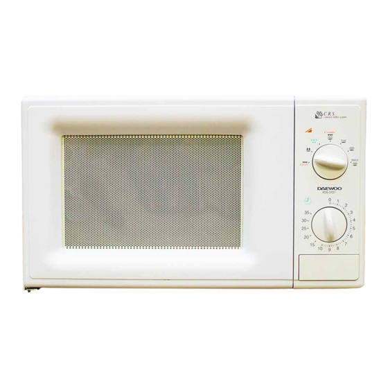
Page 5: External View
EXTERNAL VIEW 1. OUTER DIMENSION... -
Page 6: Feature Diagram
2. FEATURE DIAGRAM 1. Door seal - Door seal maintains the microwave energy within the oven cavity and prevents microwave leakage. 2. Reflector (Insulator Heater) 3. Heating Element 4. Oven cavity 5. Safety interlock system 6. Knob V.P.C - Used to select a microwave power level. 7. -
Page 7: Installation
• This appliance is supplied with cable of special type, which, if damaged, must be repaired with cable of same type. Such a cable can be purchased from DAEWOO and must be installed by a Qualified Person. 6. Examine the oven after unpacking for any damage such as: A misaligned door, broken door or a dent in cavity. -
Page 8: Operations And Functions
OPERATIONS AND FUNCTIONS 1. Connect the main lead to an electrical outlet. 2. After placing the food in a suitable container, open the oven door and put it on the glass tray. The glass tray must always be in place during cooking. 3. -
Page 9: Disassembly And Assembly
DISASSEMBLY AND ASSEMBLY Cautions to be observed when trouble shooting. Unlike many other appliances, the microwave oven is high-voltage, high-current equipment. It is completely safe during normal operation. However, carelessness in servicing the oven can result in an electric shock or possible danger from a short circuit. You are asked to observe the following precautions carefully. - Page 10 1. To remove cabinet 1) Remove three screws on cabinet back. 2) Push the cabinet backward. 2. To remove door assembly 1) Remove two screws which secure the stopper hinge top. 2) Remove the door assembly from top plate of cavity. 3) Reverse the above for reassembly.
- Page 11 3. To remove door parts. REF NO. PART CODE PART NAME DESCRIPTION Q’TY REMARK 3512203880 FRAME DOOR PP SI83C KOR-37D7 3517007300 BARRIER-SCREEN *O PET T0.125 3515204100 STOPPER HINGE *T AS KOR-63150S 3511705500 DOOR WELD ASSY KOR-61150S 3517002800 BARRIER SCREEN *I PE T0.1 3512300200 GASKET DOOR...
- Page 12 4. Method to reduce the gap between the door seal and the oven front surface. (1) To reduce gap located on part ‘A’ Loosen a screws on stopper hinge top, and then push the door to contact the door seal to oven front surface. Tighten two screws.
- Page 13 5. To remove control panel parts. REF NO. PART CODE PART NAME DESCRIPTION Q’TY REMARK 3513405510 KNOB VPC ABS XR-401 H-2938 3516725300 CONTROL-PANEL ABS SG-0760D SG-175 3515101600 SPRING FLAT SUS 301 T0.5 3517400510 COUPLER VPC KNOB 7122401211 SCREW TAPPING T2S TRS 4*12 MFZN 3517400400 COUPLER TIMER 3518204300...
- Page 14 6. To remove high voltage capacitor. 1) Remove a screw which secure the grounding ring terminal of the H.V. diode and the capacitor holder. 2) Remove the H.V. diode from the capacitor holder. 3) Reverse the above steps for reassembly. N High voltage circuit wiring 7.
- Page 15 8. To remove wind guide assembly. 1) Remove a screw for earthing. 2) Remove the noise filter from the wind guide. 3) Remove a screw which secure the wind guide assembly. 4) Draw forward the wind guide assembly. 5) Pull the fan from the motor shaft. 6) Remove two screws which secure the motor shaded pole.
- Page 16 10. To remove tray motor. 1) Remove the coupler in the cavity. 2) Turn the set upside down. 3) Cut the tray motor cover part from the base plate. 4) Remove the tray motor cover. 5) Remove a screw which secure the tray motor. 6) Remove the tray motor.
- Page 17 12. To remove heater parts. INSULATOR HEATER AS : 3513302700 REF NO. PART CODE PART NAME DESCRIPTION Q’TY REMARK 7392500008 NUT HEX 6N-2-5 SUS 3515000600 SPACER INSULATOR *I C3771BD 3513301100 INSULATOR HEATER SPP T0.8 3512803410 HEATER 230V 1000W 1S0PE47501 7002500613 SCREW MACHINE TRS 5X6 MFCR 7002400413...
-
Page 18: Interlock Mechanism And Adjustment
INTERLOCK MECHANISM AND ADJUSTMENT The door lock mechanism is a device which has been specially designed to completely eliminate microwave radiation when the door is opened during operation, and thus to perfectly prevent the danger resulting from the leakage of microwave. (1) Primary interlock switch When the door is closed, the hook locks the oven door. -
Page 19: Trouble Shooting Guide
TROUBLE SHOOTING GUIDE Following the procedure below to check if the oven is defective or not. 1. Check grounding before trouble checking. 2. Be careful of the high voltage circuit. 3. Discharge the high voltage capacitor. 4. When checking the continuity of the switches, fuse or high voltage transformer, disconnect one lead wire from these parts and check continuity with the AC plug removed. - Page 20 Does the fan motor work when you shut the door and turn the timer? Does the oven lamp light? Replace or repair oven lamp, Does the turntable turn? turntable motor. Normal reading should be approx. 0Ω If microwave do not Check continuity No Continuity Continuity...
-
Page 21: Measurement And Test
MEASUREMENT AND TEST 1. MEASUREMENT OF THE MICROWAVE POWER OUTPUT Microwave output power can be checked by indirectly measuring the temperature rise of a certain amount of water exposed to the microwave as directed below. PROCEDURE 1. Microwave power output measurement is made with the microwave oven supplied at rated voltage and operated at its maximum microwave power setting with a load of 1000±5cc of potable water. -
Page 22: Microwave Radiation Test
2. MICROWAVE RADIATION TEST WARNING : Make sure to check the microwave leakage before and after repair of adjustment. Always start measuring of an unknown field to assure safety for operating personnel from microwave energy. Do not place your hands into any suspected microwave radiation field unless the safe density level is known. Care should be taken not to place the eyes in direct line with the source of microwave energy. -
Page 23: Component Test Procedure
3. COMPONENT TEST PROCEDURE • High voltage is present at the high voltage terminal of the high voltage transformer during any cooking cycle. • It is neither necessary nor advisable to attempt measurement of the high voltage. • Before touching any oven components or wiring, always unplug the oven from its power source and discharge the capacitor. -
Page 24: Wiring Diagram
WIRING DIAGRAM... -
Page 25: Exploded View And Parts List
EXPLODED VIEW AND PARTS LIST 1. DOOR ASSEMBLY Refer to Disassembly and assembly. 2. CONTROL PANEL ASSEMBLY Refer to Disassembly and assembly. 3. TOTAL ASSEMBLY... - Page 26 PART CODE PART NAME DESCRIPTION Q'TY 3511714420 DOOR AS KOR-63D59A 3516720380 CONTROL-PANEL AS KOG-37D70S 3513302700 INSULATOR HEATER AS KOG-37150S 3510801300 CABINET SECC T0.5 7S312X40A1 SPECIAL SCREW T1 TRS 4X10 SE MFZN 3516109010 CAVITY WELD AS KOG-37150S 3516109610 CAVITY JOINT AS KOG-37150S 7392500008 NUT HEX...
- Page 27 PART CODE PART NAME DESCRIPTION Q'TY 3518570400 SWITCH S/A RELAY DWSR-1 4415A17352 SW MICRO VP-533A-OF SPNO #187 200G 4415A66910 SW MICRO VP-531A-OF/SZM-V16-FA-61 4415A17352 SW MICRO VP-533A-OF SPNO #187 200G 3513702600 LEVER LOCK 3513811730 LOCK POM NATURAL 3513601600 LAMP BL 240V 25W T25 C7A H187 7121400611 SCREW TAPPING T2S PAN 4X6 ,MFZN...
Need help?
Do you have a question about the KOG-37D7 and is the answer not in the manual?
Questions and answers