
Related Manuals for Source 1 S1-TBSU304-S


Summary of Contents for Source 1 S1-TBSU304-S
- Page 1 Commercial S1-TBSU304-S model Digital Thermostat Non-programmable with Humidity Control Optional accessories available, including Wi-Fi Owner’s Manual & Installation Instructions...
- Page 3 “OFF” prior to changing settings in setup or restoring Factory Defaults. This Source 1 thermostat has the ability to receive updates to its firmware. Periodically firmware updates are released by the manufacturer to add features and/or performance enhancements. This manual was produced reflecting the most current firmware/feature set at the time of publication, firmware rev.
- Page 4 Glossary of Terms Auto-Changeover: A mode in which the thermostat will turn on the heating or cooling based on room temperature demand. Cool Setpoint: The warmest temperature that the space should rise to before cooling is turned on (without regard to deadband). Deadband: The number of degrees the thermostat will wait, once a setpoint has been reached, before energizing heating or cooling.
-
Page 5: Table Of Contents
Table of Contents Table of Contents GET TO KNOW YOUR THERMOSTAT Get to Know Your Thermostat ............1 Quick Start ..................6 INTALLATION INSTRUCTIONS ............9 Sample Wiring Diagrams .............. 13 Test Operation ................16 USER SETUP Backlight Operation ..............17 Scrolling Display Options ............. -
Page 6: Get To Know Your Thermostat
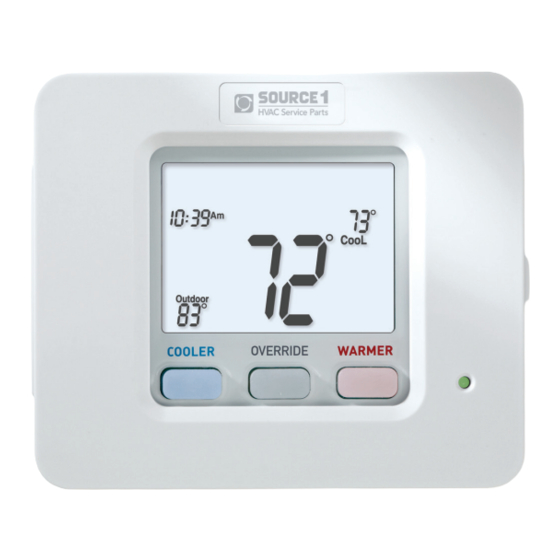
Get To Know Your Thermostat Optional Wi-Fi Module Backlit, Scrolling Display Backlit LCD Display Override Button Heat or Cool Demand Indicator Red = Heat, Green = Cool Backlit Cooler & Warmer Buttons Setup Buttons Behind Door... - Page 7 Get To Know Your Thermostat Setup Buttons...
- Page 8 Get To Know Your Thermostat Display Features 18:88 Stage Setup Step Day Night Morning Evening Override Fan On Outdoor The scrolling display will be used to help you easily navigate the setup screens in the thermostat. Clock Indicates the current time. Mode Indicators Selects the operational mode of the equipment.
- Page 9 Get To Know Your Thermostat Display Features 18:88 Stage Setup Step Day Night Morning Evening Override Fan On Outdoor Desired Set Temperature Indicates desired room temperature(s). Also displays the highest and lowest temperatures for the day. Wi-Fi icons One dot indicates the thermostat recognizes the wireless module. The full icon indicates the thermostat is currently connected to the Local access point, via the optional Wi-Fi Module.
- Page 10 Get to know your thermostat Display Features 18:88 Stage Setup Step Day Night Morning Evening Override Fan On Outdoor AuxHeat icon Indicates 2nd stage electric strip heat is being used when the thermostat is programmed for Heat Pump operation. Only the Aux icon will appear during Cool to Dehumidify to indicate Reheat operation.
-
Page 11: Quick Start
Quick Start During Setup and Programming Press the WARMER or COOLER buttons to modify the selection. Press the MODE button to advance and confirm through the setup steps. Setting the Clock Not available when wi-fi module is present Press the SET CLOCK button. Adjust the clock using the WARMER or COOLER buttons. - Page 12 Quick Start Selecting your desired temperature AUTO-CHANGEOVER MODE - Pressing the WARMER or COOLER but- tons in Auto mode will adjust both the heat and cool setpoints simul- taneously. To adjust heat and cool setpoints individually, choose HEAT mode to adjust the heat setpoint and COOL mode to adjust the cool setpoint, then return to AUTO mode.
- Page 13 Quick Start Viewing the Temperature Sensors OUTDOOR OUTDOOR TEMP - Press the OUTDOOR button to view the current outdoor temperature. If connected to a Skyport account, pressing outdoor button will show the temperatures for your location if you don’t have a wired sensor connected. Press the OUTDOOR button again to view any connected wired sensor (Remote or Supply).
-
Page 14: Intallation Instructions
Installation Instructions Remove and Replace the old thermostat To install the thermostat properly, please follow these step by step instructions. If you are unsure about any of these steps, call a qualified technician for assistance. • Assemble tools: Flat blade screwdriver, wire cutters and wire strippers. - Page 15 Installation Instructions Wire Connections If the terminal designations on your old thermostat do not match those refer to the chart below or the wiring on the new thermostat, diagrams that follow. Wire from the Install on the old thermostat Function new thermostat terminal marked connector marked...
- Page 16 Installation Instructions The Thermostat Backplate To remove the thermostat backplate: Gently separate the display from the base by pulling first from one side, then the other until the two pieces unsnap. When stat is NOT mounted on wall... W1/O/B DEHUM 24 VAC return 24 VAC common Fan relay...
- Page 17 Installation Instructions Check Dip Switches Ensure which switch is correct for your system. Dip switches are located on the back of the thermostat. ELEC RV=O RV=B GAS/ELEC HEATPUMP 1. When GAS/EL or HP is set for GAS/EL: This switch (GAS or ELEC) controls how the ELEC thermostat will control the Fan (G) terminal in heating mode.
-
Page 18: Sample Wiring Diagrams
Installation Instructions Sample Wiring Diagrams Conventional Heating and Cooling Systems 3 Wire, Heat Only 4 Wire, Cool Only Residential & Commercial 1 Stage Heating Residential & Commercial 1 Stage Cooling. with no Fan. 24VAC Power 24VAC Power 24VAC Common 24VAC Common 1st Stage Cool W1/O/B 1st Stage Heat... - Page 19 Installation Instructions Sample Wiring Diagrams Heat Pump Systems 5 Wire, 1 Stage Cooling, 1 Stage Heat 6 Wire, 1 Stage Cooling, 2 Stage Heat Residential & Commercial Heat Pump with Residential & Commercial Heat Pump with ‘O’ Reversing Valve ‘O’ Reversing Valve 24VAC Power 24VAC Power 24VAC Common...
- Page 20 Installation Instructions Sample Wiring Diagrams Humidification or Dehumidification Humidification System W1/O/B DEHUM Dehumidification Terminal DEHUM on Equipment Dry Contact and Aux Output Accessory control such as a sprinkler system W1/O/B DEHUM Accessory such as Time clock or door switch...
-
Page 21: Test Operation
Installation Instructions: Test Operation The Source 1 thermostat has a diagnostic feature that enables testing of all outputs. This feature is contained in Technician Setup. To enter Technician Setup, press and hold the SETUP button for 10 seconds until all the icons appear. Follow the next steps to view settings and test equipment. -
Page 22: User Setup Backlight Operation
User Setup: Backlight Operation How to Change Settings in the Setup Screens To enter Advanced Setup, press the SETUP button, then press MODE. Use the WARMER or COOLER buttons to adjust the value of your selection. Press MODE to advance to the next setup step. Press SETUP again to leave the setup screens. MODE SETUP Clock... -
Page 23: Scrolling Display Options
User Setup - Scrolling Screen & Display Options Scrolling Display Method (Setup Step 18) This option allows the user to choose how the scrolling text is displayed. Options are: Scrolling Non-Scrolling Scrolling Non-Scrolling Scroll Letters Slow Whole Words Slow Scroll Letters Fast Whole Words Fast Scroll Letters Slow Whole Words Slow... -
Page 24: Wi-Fi Module
User Setup - Wireless Modules Wireless Module Wireless Module The ACCESSORY STATUS button allows the user to view the status of wired and wireless accessories. For many of the wireless devices this status includes: Battery Level, Signal Strength, and Last Time Updated. If there is an optional wireless module installed, the ACCESSORY SETUP button allows the user to link or connect... - Page 25 User Setup Wi-Fi Module Wi-Fi Module Please follow the instructions included with the Wi-Fi module to connect to an Access Point or view status. The general instructions are below. Wi-Fi Module If the is present on the display then the thermosat is connected to the Wi-Fi Access Point.
-
Page 26: System Runtimes
User Setup - System Runtimes These setup steps allow the user to monitor equipment runtimes and program service alerts. Service alerts are displayed in the scrolling marquee. Runtime hours or days appear in the clock display. Setup Step FAN ON | AUTO Press and hold FAN to clear service alert messages from the scrolling marquee. - Page 27 User Setup - System Runtimes To view, set, or reset System Runtimes, press the SETUP button, then press MODE. Press MODE to advance to the desired setup step. Use the WARMER or COOLER buttons to adjust the value of your selection. Press SETUP again to leave the setup screens.
-
Page 28: Program Mode Operation
User Setup - Available Modes Selecting Your Available Modes (setup step 1) Auto-Changeover - Allows the thermostat to turn on heating or cooling based on room temperature demand. Also allows the manual selection of HEAT only or COOL only and OFF . Heat and Cool - Allows the thermostat to turn on heating or cooling depending on which one has been manually selected. -
Page 29: Installer Setup
Installer Setup Setpoint Limits (setup step 19) When this feature is at any setting other than no setpoint limits’, the heat and cool setpoints can be restricted to preset levels, set in steps 20 and 21. This feature allows the user to set 3 different levels of security: (0 - 3). No Setpoint Limits (0) - When this level is selected, no restrictions are activated. -
Page 30: Humidification & Dehumidification
Installer Setup Deadband Settings The Deadband is the number of degrees or minutes that the thermostat waits before it initiates the stages of heating or cooling. 1st Stage Deadband (setup step 29) Specifies the minimum temperature difference between the room temperature and the desired setpoint before the first stage of heating or cooling is allowed to turn on. - Page 31 Installer Setup Max Occ Dehum Overcool (Setup Step 37) - Specifies how many degrees below the Cool setpoint the air conditioning will run to satisfy a Cool to Dehumidify demand. (0˚ - 5˚) Max Unocc Dehum Overcool (Setup Step 38) - Specifies how many degrees below the Cool setpoint the air conditioning will run to satisfy a Cool to Dehumidify demand.
-
Page 32: Dry Contact Operation
Installer Setup - Information Dry Contact Operation (setup step 42 - 43) Dry Contact Polarity (setup step 42) Open (Normally Open) - The dry Closed (Normally Closed) - The dry contact is open until the connected contact is closed until the connected device closes the circuit. -
Page 33: Remote Sensor Operation
Installer Setup Control To Temp Source (setup step 31) This feature allows the use to specify which temperature sensor source(s) to be used to measure room temperature for control Thermostat: Uses the internal thermostat sensor only. Wired Remote: Uses external temperature sensor wired to the REMOTE SENSOR contacts. - Page 34 Installer Setup - Automated Demand Response Overview Source 1 thermostats support the handling of specific signals from the utility provider. The utility generated signals carry pricing information, and setback actions, that alter the comfort settings of the thermostat in order to reduce energy usage on demand. This is known as Automated Demand Response (ADR).
- Page 35 Installer Setup - Automated Demand Response The Demand Response configuration page, shown below, is where the thermostat is configured to respond to the energy provider’s signals. It also sets operational parameters for the thermostat. The left column of the ADR configuration page allows or prevents access by the utility.
- Page 36 Installer Setup - Automated Demand Response Selecting the Overview tab of the ADR page will cause a summary of ADR events to be displayed.
-
Page 37: Adr
Installer Setup - Automated Demand Response Skyport (setup step 50) Set to ON to allow access to Skyport services or to OFF to not al- low to Skyport services. (WiFi accessory is required). Visit Source1thermostats.com for more information. Local API (setup step 51) Set to ON to allow third-party software to interface with your thermostat. - Page 38 Installer Setup - Automated Demand Response Static Cool Setpoint (setup step 56) Static Heat Setpoint (setup step 57) Specifies the setpoints that will come into use during an event when the ADR ACTION is set to OBSERVE STATIC SETPOINTS Cool Setpoint Offset (setup step 58) Heat Setpoint Offset (setup step 59) Specifies how much the current setpoints in effect prior to an event will be altered during an event when the ADR ACTION is...
-
Page 39: Locking/Unlocking The Keypad
Installer Setup Locking/Unlocking the Keypad To prevent unauthorized use of the thermostat, the front panel buttons may be disabled. To disable, or ‘lock’ the keypad, press and hold the MODE button. While holding the MODE button, press the WARMER and COOLER buttons together. -
Page 40: Factory Defaults
Installer Setup - Factory Default Settings Resetting the Thermostat to the Factory Default Settings (for default values see page 38-39) If, for any reason, you desire to return all the stored settings back to the factory default settings, follow the instructions below. WARNING: This will reset all Time Period and Advanced Programming to the default settings. -
Page 41: Technician Setup
Technician Setup To enter Technician Setup, press and hold the SETUP button for 10 seconds. After all the icons appear, press MODE. The version number of the thermostat will appear in the scrolling text. Press MODE to advance to the next step. Use the WARMER or COOLER buttons to adjust the value of your selection. -
Page 42: Troubleshooting
Troubleshooting • SYMPTOM: The air conditioning does not attempt to turn on. CAUSE: The compressor timer lockout may prevent the air conditioner from turning on for a period of time. REMEDY: Consult the Owner’s Manual in the Installer Setup section to defeat the Cycles Per Hour (page 24). -
Page 43: Advanced Setup Table
Advanced Setup Table Df = Factory Default Setting Step# Description Pg# Range Heat/Cool/Auto/Off, Heat/ Available Modes Heat/Cool/Off, Cool/ Heat/Off, Cool/Off Auto/Off Backlight On, Off Off thru 7 levels of brightness Backlight Level Level 5 Night Dimmer On/Off Off thru 7 levels of brightness Night Dimmer Brightness 2 (20%) Night Dimmer Start Time... - Page 44 Advanced Setup Table Df = Factory Default Setting Step# Description Pg# Range Thermostat, Wired Remote*, Thermostat Control to Temp Source Wireless Remote, Average of Wireless Remotes, Average Thermostat and Wired Remote*, Average All Sensors. *Option only if prior step = “Remote” list of wifi sensors currently first linked Wireless Remote to Use...
-
Page 45: Warranty
Warranty One-Year Warranty - This Product is warranted to be free from defects in material and workmanship. If it appears within one year from the date of original installation, whether or not actual use begins on that date, that the product does not meet this warranty, a new or remanufactured part, at the manufacturer’s sole option to replace any defective part, will be provided without charge for the part itself provided the defective part is returned to the distributor through a qualified servicing dealer. -
Page 46: Technical Specifications
Technical Specifications S1-TBSU304-S Thermostat Controllers T8490 Manual Thermostat Controllers 20 - 30 VAC 50/60 Hz, 3.0 VA @ 24V nominal. Power Requirements Output Rating W1, W2, W3 = 0.2A max, 0.01A min, 3A inrush, 20 - 30 VAC Y1, Y2, G = 0.4A max, 0.01A min, 3A inrush, 20 - 30 VAC HUM, DEHUM, AUX = 0.1A max, 0.01A min, 3A inrush, 20 - 30 VAC... - Page 47 Patent Pending P/N 88-1345 05/19...
Need help?
Do you have a question about the S1-TBSU304-S and is the answer not in the manual?
Questions and answers