Table of Contents
Advertisement
Quick Links
Advertisement
Table of Contents

Related Manuals for Tektronix 80C12B Series


Summary of Contents for Tektronix 80C12B Series
- Page 1 80C12B Optical Sampling Module User Manual *P071299400* 071-2994-00...
- Page 3 80C12B Optical Sampling Module User Manual www.tektronix.com 071-2994-00...
- Page 4 Copyright © Tektronix. All rights reserved. Licensed software products are owned by Tektronix or its subsidiaries or suppliers, and are protected by national copyright laws and international treaty provisions. Tektronix products are covered by U.S. and foreign patents, issued and pending. Information in this publication supersedes that in all previously published material.
- Page 5 Tektronix, with shipping charges prepaid. Tektronix shall pay for the return of the product to Customer if the shipment is to a location within the country in which the Tektronix service center is located. Customer shall be responsible for paying all shipping charges, duties, taxes, and any other charges for products returned to any other locations.
-
Page 7: Table Of Contents
Table of Contents General Safety Summary ..................Environmental Considerations ................... Preface ......................Specifications....................Manual Structure..................... Related Documentation ..................viii Getting Started ...................... Instrument Requirements ..................Module Features ....................Options and Accessories ..................Installation ...................... Operating Basics....................Usage......................System Interaction .................... Front Panel Controls.................. - Page 8 Table of Contents List of Figures Figure 1: Module compartments.................. Figure 2: Connecting optical cables correctly..............Figure 3: 80C12B optical module front panel..............Figure 4: Vertical Setup dialog boxes (DSA8300)............. 80C12B Optical Sampling Module User Manual...
- Page 9 Table of Contents List of Tables Table 1: 80C12B module features ................Table 2: Standard accessories ..................Table 3: Available 80C12B filter options ................ Table 4: Available 80C12B calibration and warranty options ..........Table 5: Optional accessories ..................80C12B Optical Sampling Module User Manual...
-
Page 10: General Safety Summary
General Safety Summary General Safety Summary Review the following safety precautions to avoid injury and prevent damage to this product or any products connected to it. To avoid potential hazards, use this product only as specified. Only qualified personnel should perform service procedures. While using this product, you may need to access other parts of a larger system. - Page 11 General Safety Summary Terms in This Manual These terms may appear in this manual: WARNING. Warning statements identify conditions or practices that could result in injury or loss of life. CAUTION. Caution statements identify conditions or practices that could result in damage to this product or other property.
-
Page 12: Environmental Considerations
Union requirements according to Directives 2002/96/EC and 2006/66/EC on waste electrical and electronic equipment (WEEE) and batteries. For information about recycling options, check the Support/Service section of the Tektronix Web site (www.tektronix.com). Restriction of Hazardous This product has been classified as Monitoring and Control equipment, and is outside the scope of the 2002/95/EC RoHS Directive. -
Page 13: Preface
The capabilities of the module How to install the module How to control signal acquisition, processing, and input/output of information The latest version of this document is available at the Tektronix manuals Web site (www.tek.com/manuals). Specifications Specifications are located in the specifications and performance verification document for your main instrument. -
Page 14: Related Documentation
Preface Related Documentation This document covers installation and usage of the sampling module and its features. For information about the main instrument in which the sampling module is installed, refer to the user documents and online help provided with your main instrument. viii 80C12B Optical Sampling Module User Manual... -
Page 15: Getting Started
Getting Started The 80C12B Series Optical Sampling Module is a high-performance optical module that supports high bandwidth telecom and datacom standards from 155 Mb/s to 11.7 Gb/s in a single optical sampling module. The module is compatible with the following main instruments (mainframes):... -
Page 16: Table 1: 80C12B Module Features
Getting Started Table 1: 80C12B module features Feature Description Number of input channels Effective wavelength range 700 nm to 1650 nm Calibrated wavelength settings 850 nm, 1310 nm, 1550 nm Supported standards or data (See Table 3 on page 3.) filtering rates Typical optical bandwidth at >12 GHz (available with Options F0, 10G, or 10GP) -
Page 17: Options And Accessories
Getting Started Options and Accessories This section lists the standard and optional accessories available for the sampling modules. Standard Accessories The following accessories are shipped with the module: Table 2: Standard accessories Item Part number 80C12B Optical Sampling Module User 071-2994-XX Manual (this document) Certificate of Traceable Calibration for... -
Page 18: Table 4: Available 80C12B Calibration And Warranty Options
Getting Started Table 3: Available 80C12B filter options (cont.) Option Description FC1063 (1.0625 Gb/s) ENET1250 Gigabit Ethernet (1.250 Gb/s) FC2125 (2.125 Gb/s) OC-48/STM-16 (2.488 Gb/s) 2GBE (2.500 Gb/s) INF2500 (2.500 Gb/s) FEC2.666 Gb/s (2.666 Gb/s) 10GBASE-X4 (3.125 Gb/s) 10GFC-X4 FC-3188 (3.188 Gb/s) FC4250 (4.250 Gb/s) INF5000 (5.000 Gb/s) OBSAI6144 (6.144 Gb/s) -
Page 19: Table 5: Optional Accessories
Getting Started Optional Accessories You can order the following accessories for use with the sampling modules. See the Tektronix Web site for the current list of optional accessories: Table 5: Optional accessories Item Part number 119-4514-XX D4/PC Universal Optical Input (UCI) adapter... -
Page 20: Installation
Getting Started Installation Electrostatic Discharge Cautions CAUTION. The electrical data outputs on the optical module are subject to damage from electrostatic discharge (ESD). To prevent damage from electrostatic discharge, observe the following guidelines: Store the module, with the supplied SMA terminations installed, in a static-free container, such as the shipping container. -
Page 21: Figure 1: Module Compartments
Getting Started Optical Signal Overdrive Caution CAUTION. Circuitry in the optical module is very susceptible to damage from overdriven signals. Verify that input optical signals are within acceptable power levels for the module. Module Locations The optical modules fit in the large upper module slots of the instrument. The large compartments support single channel modules, while the small compartments support single or dual channel modules. - Page 22 Getting Started 5. Turn the hold-down screws clockwise to lock the module in place. 6. Once you have installed the module, power on the instrument. Verify that the module passes power-on tests. NOTE. When first installing a sampling module(s) or after moving a sampling module from one compartment to another, run a module compensation (Utilities >...
-
Page 23: Operating Basics
62.5/125 μm. Use UCI (universal connector interface) series adapters to couple alternate cable types to the optical module. Refer to the Tektronix Web site for details. To connect the fiber optic cable to the module optical input: 1. -
Page 24: System Interaction
Operating Basics 3. Firmly tighten the cable connector or the adapter shell. Tighten with finger pressure only. 4. To remove, loosen the cable connector or adapter shell and pull out without rotating or bending the cable or adapter. Attenuating Optical To keep the optical input power to an appropriate level, you may need to attenuate the optical signal. -
Page 25: Front Panel Controls
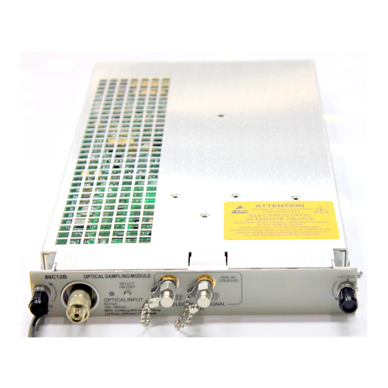
Operating Basics Front Panel Controls The following figure shows the 80C12B front panel. (See Figure 3.) Channel Selection Each channel has a SELECT channel button and an amber channel light. The button operates as follows: If the amber channel light is on, the channel is acquiring a waveform. If you push the channel button and the channel is not being acquired (for any channel or math waveform), then the instrument activates (turns on) the channel. -
Page 26: Commands From The Main Instrument Front Panel
Outputs The 80C12B module provides buffered electrical signal outputs. For clock recovery purposes, route this signal to the input of a Tektronix CR175A or CR286A Electrical Clock Recovery instrument, or to an 80A05 Electrical Clock Recovery module installed in the same mainframe. -
Page 27: Figure 4: Vertical Setup Dialog Boxes (Dsa8300)
Operating Basics Detailed information on these dialog boxes is found in the Online Help of your main instrument. Figure 4: Vertical Setup dialog boxes (DSA8300) NOTE. The user interface (UI) images in this manual are from the DSA8300 instrument. The DSA8200 UI, although different in appearance, has a similar UI layout as the DSA8300 for most functions. -
Page 28: Programmer Interface Commands
Operating Basics Programmer Interface Commands The remote programming commands for all sampling modules are documented in the Programmer Guide accessible from the instrument Help menu. User Adjustments All optical module setups, parameters, and adjustments are controlled by the main instrument. To save, recall, or change any module settings, use the main-instrument menus or front-panel controls. - Page 29 If Fail status continues after rerunning compensation, and the instrument has passed the 20-minute warm-up period, the module or main instrument may need service. Contact Tektronix Customer Service. Perform Dark-Level and Performing a dark-level calibration maximizes the accuracy of the extinction ratio and other optical automatic measurements you take.
- Page 30 Operating Basics Overview To perform optical compensations Control elements and resources Prerequisites Install the optical sampling module in the instrument. Set the acquisition system to run continuously. See the instrument user documentation and online help for details on operating the instrument controls.
- Page 31 Operating Basics Overview To perform optical compensations Control elements and resources Run the user You can optionally use a custom input signal to compensate wavelength an optical channel: gain NOTE. You must know the optical power value of the compensation custom signal.
-
Page 32: Cleaning
Use only deionized water when cleaning the menu buttons or front-panel buttons. Before using any other type of cleaner, consult your Tektronix Service Center or representative. Do not open the module case. There are no user serviceable components inside the module and cleaning the interior is not required. - Page 33 Clean both ferrule endfaces with a dry cloth tape cleaner (cassetted or in a dispenser). For safe and effective cleaning of the optical male fiber end-face exposed after removing the UCI adapter, Tektronix recommends the following method and tools. Overview To clean the optical connectors...
- Page 34 Operating Basics Overview To clean the optical connectors Related information Clean fiber Advance the fiber cleaning cassette or tape-dispenser input cleaner to expose an unused clean section of the lint-free, dry, cleaning surface. Lightly drag the clean, dry, surface of the cleaning tool cloth against the male end-face of the fiber input for a short distance (a centimeter or two).
-
Page 35: Reference
Reference This section describes available filter selections, clock recovery enabling procedures, and optical bandwidths. Wavelength, Filter, and Bandwidth Selection See Tables 1 and 3 for available wavelength, filter, and bandwidth information. (See Table 1 on page 2.) (See Table 3 on page 3.) To select the optical wavelength, open the Vertical Setups menu. - Page 36 Reference For electrical bandwidths the reference of a system is commonly the response of the system to a sinusoidal frequency at or near DC. The point at which the system response (power) is at one half would therefore be: In terms of frequency, voltage, and resistance the bandwidth is expressed as: where V(f) is the RMS of the voltage swing response at the bandwidth frequency, and V(DC) is the RMS voltage swing response at a frequency approaching DC.
- Page 37 Reference Bandwidth for Unfiltered The curve calculation of frequency response for the unfiltered frequency settings (for example, 2 GHz, 2.5 GHz, 21 GHz, 12.5 GHz, 14 GHz, 20 GHz, 30 GHz, Frequency Settings 40 GHz, 50 GHz, 65 GHz, and 80 GHz) uses the definition for dB and optical bandwidth: –3 dB = 10 log(vertical swing at frequency / vertical swing at DC) Bandwidth for Reference...
- Page 38 Reference 80C12B Optical Sampling Module User Manual...
-
Page 39: Glossary
Glossary Accuracy The closeness of the indicated value to the true value. Analog-to-Digital Converter A device that converts an analog signal to a digital signal. Attenuation A decrease in magnitude (for optical systems this is usually optical power) of a signal. Autoset A means of letting the instrument set itself to provide a stable and meaningful display of a given waveform. - Page 40 Glossary Common Mode A circumstance where a signal is induced in phase on both sides of a differential network. Decibel: a method of expressing power or voltage ratios. The decibel scale is logarithmic. It is often used to express the efficiency of power distribution systems when the ratio consists of the energy put into the system divided by the energy delivered (or in some cases, lost) by the system.
- Page 41 Glossary Extinction Ratio The ratio of two optical power levels of a digital signal generated by an optical source. P is the optical power level generated when the light source is high, and P is the power level generated when the light source is low. FEC: Forward Error Correction Additional bits and/or coding added to a data stream to allow for automatic error detection and correction at the receiving end.
- Page 42 Glossary Multimode Cable A thick cored optical fiber (compared to single mode cable) that can propagate light of multiple modes. OMA (Optical Modulation Amplitude) The difference between the average power levels of the logic 1 level, High, and the logic 0 level, Low, of the optical pulse signal. The levels are the Means of the logical levels sampled within an Aperture of the logical 1 and 0 regions of the pulse.
-
Page 43: Index
Index Accessories, 3 Dark-level compensation Main instrument commands, 12 list, 3 how to perform, 15 Manuals optional, 5 Data part numbers, 3 standard, 3 recovery, 21 Measurement accuracy Accuracy, 25 dB, 26 optimizing, 14 optimizing, 14 dBm, 26 Mode, 27 Adjustments, 14 Decibel, 26 Modulation, 27... - Page 44 Index Programmer interface, 14 SMA connector torque, 21 User wavelength compensation Protocol, 28 Specifications, vii how to perform, 15 Standard accessories, 3 System interaction, 10 Recovered Vertical compensation clock, 28 how to perform, 14 Reference, 21 Torque (BUFFERED connectors), 21 Trigger, 28 Waveform, 28 Safety Summary, iv...
Need help?
Do you have a question about the 80C12B Series and is the answer not in the manual?
Questions and answers