
Subscribe to Our Youtube Channel
Related Manuals for Tektronix 80A05


Summary of Contents for Tektronix 80A05
- Page 1 User Manual 80A05 Electrical Clock Recovery Module 071-1467-00 This document applies to firmware version 2.0.0 and above. www.tektronix.com...
- Page 2 Copyright © Tektronix, Inc. All rights reserved. Tektronix products are covered by U.S. and foreign patents, issued and pending. Information in this publication supercedes that in all previously published material. Specifications and price change privileges reserved. Tektronix, Inc., P.O. Box 500, Beaverton, OR 97077-0001 TEKTRONIX and TEK are registered trademarks of Tektronix, Inc.
- Page 3 Tektronix, with shipping charges prepaid. Tektronix shall pay for the return of the product to Customer if the shipment is to a location within the country in which the Tektronix service center is located.
-
Page 5: Table Of Contents
..........80A05 Electrical Clock Recovery Module User Manual... - Page 6 Table of Contents 80A05 Electrical Clock Recovery Module User Manual...
-
Page 7: General Safety Summary
WARNING. Warning statements identify conditions or practices that could result in injury or loss of life. CAUTION. Caution statements identify conditions or practices that could result in damage to this product or other property. 80A05 Electrical Clock Recovery Module User Manual... - Page 8 CAUTION indicates a hazard to property including the product. Symbols on the Product. The following symbols may appear on the product: CAUTION WARNING Protective Ground (Earth) Terminal Refer to Manual High Voltage 80A05 Electrical Clock Recovery Module User Manual...
-
Page 9: Preface
Preface This is the user manual for the 80A05 Electrical Clock Recovery module. The manual covers capabilities, installation, operation, and specifications of the module. Manual Structure This manual is composed of the following chapters: H Getting Started shows you how to configure and install your module and lists standard and optional accessories. -
Page 10: Contacting Tektronix
This phone number is toll free in North America. After office hours, please leave a voice mail message. Outside North America, contact a Tektronix sales office or distributor; see the Tektronix web site for a list of offices. 80A05 Electrical Clock Recovery Module User Manual... -
Page 11: Getting Started
Tektronix electrical modules. The 80A05 Electrical Clock Recovery Module provides a solution for triggering the mainframe from single-ended or differential electrical signals. The 80A05 can also be used as a general purpose clock recovery solution. - Page 12 CAUTION. To prevent electrostatic damage to the 8000 Series instrument and module, follow the precautions described in this manual and the manuals accompanying your instrument. (See Electrostatic Discharge starting on page 5.) 80A05 Electrical Clock Recovery Module User Manual...
-
Page 13: Options And Accessories
Standard Accessories The following accessories are shipped with the instrument: Table 2: Standard accessories Item Part number 80A05 Electrical Clock Recovery Module User Manual 071-1467-xx (5) SMA, male, 50 Ω termination caps. Option 10G (6) 011-0182-xx Transit case, ESD protective... -
Page 14: Installation
Getting Started Installation The 80A05 module fits into one of the large module compartments on the front panel of an 8000 Series instrument. See Figure 1. To install a module, first power off the instrument using the front-panel On/Standby switch. Then place the module in a compartment, and slowly push it in with firm pressure. -
Page 15: Electrostatic Discharge
To prevent damage to the module or instrument, do not apply a signal outside the Maximum Input Voltage Swing for your module. Static Controlled For information on creating a static-controlled workstation, consult the Electron- Workstation ic Industries Association document, EIA-625; Requirements for Handling Electrostatic-Discharge-Sensitive (ESDS) Devices. 80A05 Electrical Clock Recovery Module User Manual... - Page 16 Getting Started 80A05 Electrical Clock Recovery Module User Manual...
-
Page 17: Operating Basics
(see Figure 1 on page 4 for the location of the ejectors). Power LED There is one LED on the front panel of the 80A05 module that indicates the clock recovery circuitry is on and programmed to the requested bit rate. The 80A05 module receives power through the TEKPROBE-Sampling interface. -
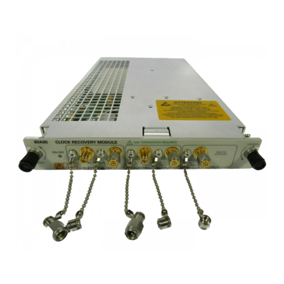
Page 18: Input And Output Connectors
Figure 2: 80A05 module front panel Figure 3: 80A05- 10G module front panel Input and Output The connectors on the front panel of the 80A05 module provide connections for Connectors the input and output signals. All connectors are SMA female connectors. -
Page 19: System Interaction
All module setups, parameters, and adjustments are controlled by the instrument. To save, recall, or change any module settings, use the instrument menus or front-panel controls or consult the CSA8000 & TDS8000 User Manual or CSA8000 & TDS8000 Online Help 80A05 Electrical Clock Recovery Module User Manual... - Page 20 Operating Basics 80A05 Electrical Clock Recovery Module User Manual...
-
Page 21: Specifications
Specifications This section contains specifications for the 80A05 Electrical Clock Recovery Module. All specifications are guaranteed unless noted as “typical.” Typical specifications are provided for your convenience but are not guaranteed. All specifications apply to all models of module unless noted otherwise. To meet... - Page 22 Supported data rates OC192/STM64 9.953 Gb/s and formats added 10GBase-W 9.953 Gb/s with Option 10G 10GBase-R 10.31 Gb/s 10G FibreChannel 10.51 Gb/s G.975 FEC 10.66 Gb/s G.709 FEC 10.71 Gb/s 10GbE w/FEC 11.10 Gb/s 80A05 Electrical Clock Recovery Module User Manual...
- Page 23 Does not include connectors, connector savers, connector covers, push buttons, or lock-down hardware protruding from the front or rear panels. Construction material Chassis aluminum alloy; Front panel plastic laminate; Circuit boards glass-laminate; Cabinet sleeve aluminum Cabinet end covers aluminum 80A05 Electrical Clock Recovery Module User Manual...
- Page 24 The instrument meets or exceeds the EMC requirements of the following standards: EN61326- - 1 European Community Requirements IEC 1000- - 4- - 2 Electrostatic Discharge Immunity 4 kV contact discharge 8 kV air discharge Performance criteria B 80A05 Electrical Clock Recovery Module User Manual...
- Page 25 Specifications 80A05 Electrical Clock Recovery Module User Manual...
Need help?
Do you have a question about the 80A05 and is the answer not in the manual?
Questions and answers