
Related Manuals for LG CBV42


Summary of Contents for LG CBV42
- Page 1 OWNER'S MANUAL LG CLOUD V SERIES BOX Please read the safety information carefully before using the product. LG Cloud V Series Box Model List CBV42 www.lg.com...
-
Page 2: Table Of Contents
Table of Contents Table of Contents ASSEMBLING AND PREPARING Unpacking Parts and Buttons Product Installation - Using in Horizontal Position - Using in Vertical Position - Mounting on the Back of the Monitor CONNECTING LAN/ PERIPHERALS - LAN Connection - DisplayPort Connection - Extended Monitor Connection - Peripheral device connection TROUBLESHOOTING... -
Page 3: Assembling And Preparing
Stand Base Mount Bracket 4 Screws CAUTION Only use an approved LG power adapter. Damage caused by other power adapters is not covered by warranty. NOTE Note that the components may look different from those shown here. Without prior notice, all information and specifications in this manual are subject to change to improve the performance of the product. -
Page 4: Parts And Buttons
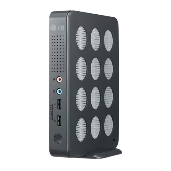
ASSEMBLING AND PREPARING Parts and Buttons Power Indicator & Power Button On: Power On Off: Power Off Front Side Rear Side Input Connectors... -
Page 5: Product Installation
ASSEMBLING AND PREPARING Product Installation Mounting on the Back of the Monitor Using in Horizontal Position Fix the mount bracket on the back of the monitor with 4 screws as illustrated below. NOTE If this product is used with upside down, it may not work properly. -
Page 6: Connecting Lan/Peripherals
Connecting LAN/Peripherals CONNECTING LAN/PERIPHERALS LAN Connection DisplayPort Connection Connect the router or switch to the monitor using a Transmits digital video signals to the monitor. Con- LAN cable as illustrated below. nect the product using the DisplayPort cable as illustrated below. DP OUT DP IN MONITOR 1... -
Page 7: Extended Monitor Connection
DP IN MONITOR 1 Connecting LAN/Peripherals Extended Monitor Connection Peripheral device connection Transmits digital video signals to the monitor. Con- Connect peripheral devices to the monitor using nect the product using the DVI cable as illustrated USB, microphone and headphone ports. below. - Page 8 Connecting LAN/Peripherals NOTE Peripheral devices are sold separately. The USB ports can be used to connect the keyboard, mouse, and other USB devices. For an angle plug earphone/microphone, it is difficult connect it with a peripheral device, so use a straight type. Angle Type Straight Type NOTE...
-
Page 9: Troubleshooting
TROUBLESHOOTING TROUBLESHOOTING Nothing is displayed on the screen Is the power adapter of the Box y Check if the power cord is correctly plugged in to the power outlet. plugged in ? Is the power indicator on? y Check the power indicator. Is the power indicator displaying as y Adjust the brightness and the contrast of the connected monitor. -
Page 10: Specifications
0.6 kg Packaging) AC/DC adapter Type ADS-40SG-19-3 19025G, manufactured by SHENZHEN HONOR ELECTRONIC Or Type LCAP21, manufactured by LIEN CHANG ELECTRONIC ENTERPRISE Or Type PSAB-L203A, manufactured by LG Innotek Co.,Ltd Output: 19 V 1.3 A Environmental Operating Condition Temperature: 10°C to 35°C; Humidity: 10% to 80%... -
Page 11: Using Cloud Solution
Using CLOUD Solution USING CLOUD SOLUTION NOTE Menus and functions in CLOUD mode may be slightly different depending on the firm- ware version.You can download the user manual for each version from the Teradici homepage: http://www.teradici.com To check the firmware version, see page <28>. - Page 12 Using CLOUD Solution If you select the Connect button, the connection Configuration Window session is started. When the connection is pend- In the Configuration window, the administrator can ing, the "Discovering hosts, please wait…" mes- access the window tabs that contain the settings to sage is displayed on the OSD local GUI.When the configure and manage the portal environment.
- Page 13 Using CLOUD Solution Network Tab y Gateway The Network tab allows the administrator to config- The Gateway field contains the gateway IP ad- ure the portal network parameters. dress of the device. If DHCP is disabled, this field is required. If DHCP is enabled, this field cannot be edited.
- Page 14 Using CLOUD Solution <IPv6> Tab y Secondary DNS Server The IPv6 tab is used when the portal is connected The Secondary DNS Server field contains the sec- to the network configured with the IP v6. ondary DNS IP address of the device. This field is optional.
- Page 15 Using CLOUD Solution Discovery Tab Label Tab The Label tab allows the administrator or host to The Discovery tab allows the administrator to eas- add customized information to the portal. ily find a portal in the PCoIP system. NOTE NOTE The portal label parameters can also be con- The Discovery parameters can also be con- figured using the Webpage Administration...
- Page 16 Using CLOUD Solution Session Tab See below for information how to set for each op- The Session tab allows the administrator to set the tion. method to connect the device to a peer device. NOTE The Session parameters can also be con- figured using the Webpage Administration Interface.
- Page 17 Using CLOUD Solution y Direct to Host + SLP Host Discovery You can view the screen of the host PC by discov- ering the host PC within the network and estab- lishing 1:1 connection between the PCI host card connected to the host PC and the portal. <Figure 2-13: Advanced Settings for Direct to Host>...
- Page 18 Using CLOUD Solution View Connection Server In the Session tab, you can select to enable the user client to access the VMware View Connec- tionServer. To do this, select View Connection Server for Connection Type. <Figure 2-15: Advanced Settings for Direct to Host + SLP Host Discovery>...
- Page 19 Using CLOUD Solution Prefer GSC-IS If this option is selected, the GCS-IS interface is used when a smart card supports more than one interface. If the smart card supports only one interface, it is not used. NOTE This setting is provided only when a smart card is used.
- Page 20 Using CLOUD Solution y View Connection Server with Auto-Logon In the Session tab, you can select to enable the user client to automatically access the VMware View Connection Server.To do this, select View Connection Server with Auto-Logon for Connection Type. <Figure 2-19: Advanced Settings for View Connec- tion Server with Auto-Logon>...
- Page 21 Using CLOUD Solution Prefer GSC-IS y View Connection Server + Kiosk If this option is selected, the GSC-IS interface Select View Connection Server + Kiosk to use is used when a smart card supports more than the kiosk mode. You can configure the View Con- one interface.
- Page 22 Using CLOUD Solution Enable Preparing Desktop Overlay If this option is selected, the "Preparing Desk- top" message is displayed on the screen when the user is logged in. Disconnect Message Filter This option determines the type of message to display when a session is disconnected. - Show All: Shows all the error messages.
- Page 23 Using CLOUD Solution Enable Preparing Desktop Overlay If this option is selected, the "Preparing Desk- top" message is displayed on the screen when the user is logged in. Disconnect Message Filter This option determines the type of message to display when a session is disconnected. - Show All: Shows all the error messages.
- Page 24 Using CLOUD Solution Language Tab The Language tab allows the administrator to set the OSD language. NOTE The Language parameters can also be con- figured using the Webpage Administration Interface. <Figure 2-25: Advanced Settings for Connection Management Interface> Enable Peer Loss Overlay If this option is selected, the "Network Connection Lost"...
- Page 25 Using CLOUD Solution OSD Tab Display Tab The OSD tab allows the administrator to modify the The Display tab allows the user to configure the On Screen Display (OSD) parameters. EDID function of the monitor. NOTE NOTE The OSD parameters can also be configured The Enable display override function can be using the Webpage Administration Interface.
- Page 26 Using CLOUD Solution Reset Tab Diagnostics Window The Reset tab allows the administrator to reset all In the Diagnostics window, the administrator can configurable parameters stored in Flash. access the window tab to diagnose the portal. The Diagnostics window has the following tabs: y Event Log NOTE y Session Statistics...
- Page 27 Using CLOUD Solution Session Statistics Tab PCoIP Processor Tab The Session Statistics tab allows the administrator The PCoIP Processor tab allows the administrator to view the PCoIP specific statistics of the last ac- to view the portal PCoIP processor's uptime since tive PCoIP session from the portal.
- Page 28 Using CLOUD Solution Ping Tab The Ping tab allows the administrator to perform a ping test to the device and check if it can reach the overall IP network. This is useful to check whether the device can reach the host. NOTE The Ping tab has no corresponding menu in to the Webpage Administration Interface of...
- Page 29 Using CLOUD Solution User Settings Window Mouse Tab In the User Settings window, the administrator can The Mouse tab allows the user to modify the OSD access the tab to select the mouse and keyboard and RDP session's mouse cursor speed setting. and define the PCoIP image quality.
- Page 30 Using CLOUD Solution Keyboard Tab Image The Keyboard tab allows the user to modify the The Image tab allows a user to change the image OSD and RDP session's keyboard repeat setting. settings on the PCoIP system. NOTE NOTE The Image parameters can also be con- The OSD keyboard setting does not affect figured using the Webpage Administration the keyboard settings when a PColP session...
- Page 31 Using CLOUD Solution y Touch Screen Tab y Display Topology Tab The Touch Screen tab allows the user to specify The Display Topology tab allows the user to specify the touch sensitivity and alignment when the moni- the position and alignment of a connected second- tor supports the touch screen function.
- Page 32 In addition to the source code, all referred license terms, warranty disclaimers and copyright notices are available for download. LG Electronics will also provide open source code to you on CD-ROM for a charge covering The product label contains necessary the cost of performing such distribution (such information for after-service.
Need help?
Do you have a question about the CBV42 and is the answer not in the manual?
Questions and answers