Table of Contents
Advertisement
Quick Links
4-696-253-11(1)
Network Camera
Installation Manual
Before operating the unit, please read this manual thoroughly and
retain it for future reference.
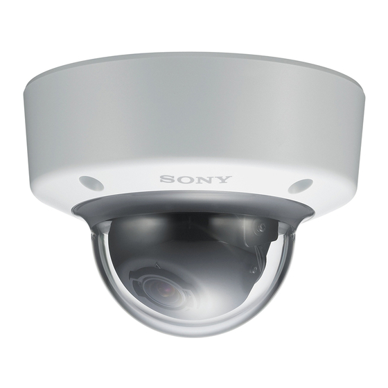
SNC-VM641/EM641
© 2017 Sony Corporation
A
B
C
D
85.7 (3
/
)
3
8
Hole for connecting cables
ø50 (2)
Horizontal mark
Hole for installing the
bracket
Vertical mark
Unit: mm (inches)
About the Manuals
Safety Regulations (included)
The Safety Regulations describes notes for the secure usage of camera. Be sure
to read it.
Installation Manual (this document)
Describes the names and functions of parts and controls of the Network Camera,
gives connection examples and explains how to set up the camera. Be sure to
read the Installation Manual before operating.
The illustration of SNC-VM641 is used for example purpose.
An I/O cable or power input cable is not supplied for SNC-EM641.
Electronic Instruction Manual (Web)
ˎ
How to control the camera via a web browser
ˎ
How to setup the camera
Operate the camera referring to the guide above after having installed and
connected the camera properly based on the Installation Manual.
Assigning the IP address
1
Download the installer for "SNC toolbox" to a folder from the download
site.
2
Install the SNC toolbox.
Unzip the ZIP file of the downloaded installer.
Double-click "SncToolbox_Setup.exe. " For details on installing and use refer to
the Application Guide.
3
Assign an IP address.
Assign an IP address using the installed SNC toolbox. For details, see "Using
SNC toolbox" – "Assign an IP address" in the Application Guide.
Tip
SNC toolbox stands for Sony Network Camera toolbox.
Location and Function of Part
Side
The cables below are not connected when the unit comes from the factory.
SNC-VM641: , , ,
SNC-EM641: ,
Audio cable (supplied)
The connector with the longer cable (SP) is used for the line output connector,
and the shorter cable (MIC) is used for the microphone/line input connector.
ˎ
SP terminal (minijack, monaural)
Connect a commercially available speaker system with a built-in amplifier.
ˎ
MIC terminal (minijack, monaural)
Connect a commercially available microphone. This jack supports plugin-
power microphones (rated voltage: 2.5 V DC).
I/O (Input/Output) cable (supplied only for SNC-VM641)
This cable is provided with two sensor inputs and two alarm outputs.
The wires of the cable control the following signals.
Color of wire
Name
Red
Sensor In 1+
White
Sensor In 2+
Black
Sensor In – (GND)
Yellow
Alarm Out 1+
Brown
Alarm Out 1–
Green
Alarm Out 2+
Blue
Alarm Out 2–
For details on each function and required settings, see the User's Guide.
For the wiring, see "Connecting the I/O Cable."
Power input cable (supplied only for SNC-VM641)
Connect this cable to a 24 V AC or 12 V DC power supply system.
You can screw an extension cable in the connector tip attached at the end of the
cable. (-1)
BNC cable (supplied)
Outputs a composite video signal.
Wiring cover
When you wire indoors, remove this cover and feed the cables through it.
Caution
Take care not to trap the cables between the camera and the ceiling or the wall. If
the cable is trapped, it may cause a fire or electric shock due to breaking.
Inside
Items and are not supported for SNC-EM641.
Camera unit
MONITOR output jack
Connect this jack to a video input connector of a video monitor. You can adjust
the camera or lens while looking at the image on the video monitor. After
adjusting the camera or lens, disconnect the cable.
Camera unit mounting screws (2 positions)
Make sure to tighten the screws securely when installing the camera.
Camera head fixing screw (tilt)
Firstly, loosen the screw and point the camera head in the desired direction, then
tighten the screw to secure in place.
SD card slot
This slot is used for optional SD memory cards.
Image data in the camera can be recorded to a memory card by inserting it into
the slot.
When inserting, point the contact area at the rating label side (referring to the
illustration), and be sure to insert it completely. (-1)
This unit is only compatible with SD and SDHC memory cards.
Note
For inquiries regarding verified SD memory cards, contact your authorized Sony
dealer.
NTSC/PAL switch
Switching the video output.
After setting the switch, reboot the camera unit.
ZOOM/FOCUS switch
Use this switch to adjust lens' zoom and focus. Slide the switch lever to select the
desired function.
[W] WIDE: Zoom out
[T] TELE: Zoom in
[N] NEAR: Focus on a nearby subject
[F] FAR: Focus on a distant subject
Hold down the center of the ZOOM/FOCUS switch for a moment to focus
automatically.
Reset switch
To reset the camera to the factory default settings, hold down this switch with a
point and supply the power to the camera.
NETWORK indicator (Green/Orange)
The indicator lights up or flashes when the camera is connected to the network.
The indicator is off when the camera is not connected to the network.
POWER indicator (Green)
When the power is supplied to the camera, the camera starts checking the
system. If the system is normal, this indicator lights up.
AC / DC IN (power input) connector (SNC-VM641 only)
Connect the supplied power input cable to this connector.
Rating Label
This label shows the name of device and its electric rating.
AUDIO connector
Connect the supplied audio cable to this connector.
Camera head fixing screw (pan)
Firstly, loosen the screw and point the camera head in the desired direction, then
tighten the screw to secure in place.
mark
Indicates the image direction.
Lens
EXT CTRL (external control input/output) connector (SNC-VM641
only)
Connect the supplied I/O cable to this connector.
LAN network port (RJ-45)
Connect a network cable (UTP, category 5) to this port to communicate with a
network or PoE* system.
For details on connection, see the Instruction Manual of the power supply
equipment.
(*PoE stands for Power over Ethernet. It is pursuant to IEEE802.3af.)
VIDEO OUT (video output) connector
Connect the supplied BNC cable to this connector.
Preparations
Connecting the Supplied Cables to the Camera
Before installation, connect the supplied cables to the camera as required for
your usage and wire them.
Connect the cables to the connectors on the camera unit.
Power input cable: to AC/DC IN connector (SNC-VM641 only)
Audio cable
BNC cable
I/O cable (SNC-VM641 only)
Note
Do not pull on any cables forcefully, as a connection may become loose.
Installation
WARNING
ˎ
If you attach the camera in the height such as the wall or the ceiling, etc.,
entrust the installation to an experienced contractor or installer.
ˎ
If you install the camera on the ceiling, ensure that the ceiling is strong
enough to withstand the weight of the camera plus the bracket and then
install the camera securely. If the ceiling is not strong enough, the camera may
fall and cause serious injury.
ˎ
To prevent the camera from falling, make sure to attach the supplied wire
rope.
If you attach the camera to the ceiling, check periodically, at least once a year,
ˎ
to ensure that the connection has not loosened. If conditions warrant, make
this periodic check more frequently.
Deciding the Installation Location of the Camera
After deciding the direction in which the camera will shoot, make the required
hole (ø 50 mm (2 inches)) for the connecting cables using the supplied template.
Then decide the two or four mounting hole positions to install the bracket.
Mounting screws
The supplied bracket is provided with ø 4.5 mm (
3
/
inch) mounting holes. Install
16
the bracket on a ceiling or wall with screws through two or four mounting holes:
two 83.5 mm (3
9
/
inches)-pitched holes or four 85.7 mm (3
32
holes. The required mounting screws differ depending on the installation location
and its material. Use commercially-available screws.
Steel wall or ceiling: Use M4 bolts and nuts. (Hexagon head bolt should not be
used.)
Wooden wall or ceiling: Use M4 tapping screws. The panel thickness must be
15 mm (
/
inch) or more.
5
8
Concrete wall: Use anchors, bolts and plugs suitable for concrete walls. (Head
shape of M4 bolt: Pan head screw or hexagon head bolt should not be used.)
Junction box: Use screws to match the holes on the junction box. (Head shape
of screw: ø 7 mm (
/
inch) Height 4 mm (
/
inch) or less)
9
3
32
16
WARNING
The required mounting screws differ depending on the installation location and
its material. If you do not secure the camera with the appropriate mounting
screws, the camera may fall off.
3
/
inches)-pitched
8
Advertisement
Table of Contents

Related Manuals for Sony SNC-VM641


Summary of Contents for Sony SNC-VM641
- Page 1 (-1) 85.7 (3 This unit is only compatible with SD and SDHC memory cards. Note Hole for connecting cables For inquiries regarding verified SD memory cards, contact your authorized Sony ø50 (2) dealer. NTSC/PAL switch Horizontal mark Switching the video output.
- Page 2 Minimum illumination View-DR Off/VE*Off/Auto gain maximum rate Dome casing For SNC-VM641, it is possible to connect the LAN port of the camera to a router MAX/30 IRE (IP) /30 fps or hub in the network using a commercially-available network cable.
Need help?
Do you have a question about the SNC-VM641 and is the answer not in the manual?
Questions and answers