Table of Contents
Advertisement
Quick Links
VSS Nederland
Owner´s Manual
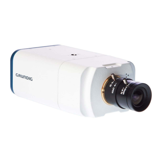
IP Cameras & Domes
GCI-H0503B
GCI-H0602B
GCI-K0503B
GCI-K0503B. 11.1.28.01.2011
© ASP AG
VSS Nederland B.V.
-
Telfordstraat 11m
Video Systems
720P HD IP Col/B&W Camera WDR Low Light
720P HD IP Colour Camera
1080P Full HD IP Col/B&W Camera
-
8013 RL Zwolle
-
Tel.: +31 38 42 89 420
-
Fax: +31 38 42 89 429
-
E-mail: info@vssnederland.nl
e
Advertisement
Table of Contents

Related Manuals for VSS Nederland GCI-H0503B

Summary of Contents for VSS Nederland GCI-H0503B
- Page 1 GCI-H0602B 720P HD IP Colour Camera GCI-K0503B 1080P Full HD IP Col/B&W Camera GCI-K0503B. 11.1.28.01.2011 © ASP AG VSS Nederland B.V. Telfordstraat 11m 8013 RL Zwolle Tel.: +31 38 42 89 420 Fax: +31 38 42 89 429 E-mail: info@vssnederland.nl...
-
Page 3: Table Of Contents
Content: 1. Introduction 18. Factory Default 2. Important Safety Instructions 19. Software Version 3. Package Contents 20. Software Upgrade 4. Installation 21. Maintenance 1. Camera Overview 10. Streaming Settings 2. System Requirements 1. Video Format 3. Lens Mounting 2. Video Compression 4. -
Page 4: Important Safety Instructions
Camera’s flexible platform, the camera can be applied in various installation locations including shops, stores, banks, parking lots, factories and building surveillance. The built-in Wide Dynamic Range (WDR) function of the model GCI-H0503B allows getting crystal clear images even in extreme conditions. This IP Camera is highly sensitive and has a good low-light performance. -
Page 5: Installation
9. Micro SD Card slot: For video and snapshots storage 10. For GCI-H0602B: 12V connector / For GCI-K0503B and GCI-H0503B: AC 24V/DC 12V Connector (Please refer to the table below for wiring the AC 24V/DC 12V camera with the supplied power cable). -
Page 6: Lens Mounting
NOTE: If using PoE, make sure the Power Sourcing Equipment (PSE) is in use in the network. Power Connection for GCI-K0503B and GCI-H0503B: Please refer to section 4.1. Camera Overview for power wiring. Additionally, if using PoE, make sure Power Sourcing Equipment (PSE) is in use in the network. -
Page 7: Alarm Application
Check the status of the link indicator and activity indicator LEDs; if the LEDs are unlit, please check LAN connection. Green Link Light indicates good network connection. Orange Activity Light flashes for network activity indication. 4.6. Alarm Application The camera equips one alarm input and one relay output for alarm application. Refer to alarm pin definition below to connect alarm devices to the IP Camera if needed. - Page 8 Deleting Temporary Internet Files : To improve the browser performance, it is suggested to clean up all the files in the Temporary Internet Files. The procedure is as follows (for other web browsers please read the corresponding manuals): STEP 1: Click on the “Tools” tab and select the option “Internet Options”. STEP 2: Click on “Delete”, then tap the “Delete Files”...
-
Page 9: Accessing The Camera
6. Accessing the Camera For initial access to the IP Camera, users can search the camera through the installer program: GRUNDIG Finder.exe, which can be found on the supplied CD. GRUNDIG Finder Software Setup : Step 1: Double-click on the program GRUNDIG Finder.exe (see the icon below); its window will appear as shown below. - Page 10 Device Search : Step 3: Click “Find Device” again, and all the IP devices found will be listed on the page, as shown in the picture below. The IP Camera’s default IP address is: 192.168.1.1. Step 4: Double-click or right-click and select “Browse” to access the camera directly via web browser. Step 5: Then the dialogue box for entering the default username and password (as shown below) will appear for logging in to the IP Dome Camera.
- Page 11 NOTE: ID and password are case sensitive. It is strongly advised that administrator’s password be altered for security concerns. Refer to section 9.2. Security for further details. Additionally, users can change the IP Camera’s network property, either DHCP or Static IP, directly in the device finding list.
- Page 12 Step 4: Click the “Find Device” button to search all the devices. Then select the IP Camera with the correct MAC address. Double-click on the IP Camera, and the login window will come out. Step 5: Enter User name and Password to access the IP Camera. Installing the GRUNDIG Viewer Software Online : For initial access to the IP Camera, a client program, DC Viewer, will be automatically installed to your PC when connected to the IP Camera.
- Page 13 Once logged in to the IP Camera, users will see the Home page as shown below: Administrator/User Privileges : “Administrator” represents the person who can configure the IP Camera and who authorizes users to have access to the camera; “User” refers to whoever has access to the camera with limited authority, i.e. to enter Home and Camera setting pages.
-
Page 14: Browser-Based Viewer Introduction
7. Browser-based Viewer Introduction The picture below shows the Home page of the IP Camera’s viewer window. There are five tabs: Home, System, Streaming, Camera and Logout (on the left hand side). Home : Users can monitor the live video of the targeted area. System setting : The administrator can set host name, system time, admin password, network related settings, etc. -
Page 15: Home Page
8. Home Page In the Home page, there are several function buttons right down the displayed image. NOTE: Please note that the function buttons will vary depending on the camera model. Display Mode (Screen Size Adjustment) : Image display size can be adjusted to x1/2 and full screen. Digital Zoom Control : In the full screen mode, users can implement digital PTZ by rotating the mouse wheel (for zoom in/out), and drag the mouse into any direction. -
Page 16: System Related Settings
9. System Related Settings The picture below shows all categories under the “System” tab. Each category in the left column will be explained in the following sections. NOTE: The “System” configuration page is only accessible by the Administrator. 9.1. Host Name and System Time Setting Press the first category: <System>... -
Page 17: Security
Host Name : The name is for camera identification (max. 30 characters). If alarm function (see section 9.8. Application) is enabled and is set to send an alarm message by Mail/FTP, the host name entered here will display in the alarm message. - Page 18 Add User : Type the new user's name and password and click <Add> to add the new user. The user name can have up to 16 characters, the password up to 14 characters. The new user will be displayed in the user name list. There is a maximum of twenty user accounts.
- Page 19 <HTTPS> : <HTTPS> allows secure connections between the IP Camera and the web browser using the <Secure Socket Layer (SSL)> or the <Transport Layer Security (TLS)>, which prevent camera settings or Username/Password info from snooping. It is required to install a self-signed certificate or a CA-signed certificate for implementing <HTTPS>.
- Page 20 Create Self-signed Certificate : Before a CA-issued certificate is obtained, users can create and install a self-signed certificate first. Click the <Create> button under “Create self-signed certificate” and provide the requested information to install a self-signed certificate for the IP Camera. Please refer to the last part of this section: Provide the Certificate Information for more details.
- Page 21 Create Certificate Request : Click the “Create Certificate Request” button to create and submit a certificate request in order to obtain a signed certificate from CA. When the request is complete, the subject of the Created Request will be shown in the field. Click “Properties” below the Subject field, copy the PEM-formatted request and send it to your selected CA.
- Page 22 Provide the Certificate Information : To create a Self-signed HTTPS Certificate or a Certificate Request to CA, please enter the information as requested: - Country: Enter a 2-letter combination code to indicate the country the certificate will be used in. For instance, type in “GB” to indicate Great Britain.
- Page 23 - Organisation Unit: Enter the name of the organisational unit to which the entity identified in “Common Name” belongs. - Common Name: Indicate the name of the person or other entity that the certificate identifies (often used to identify the website). - Valid days (Self-signed Certificate Only): Enter the period in days (1~9999) to indicate the valid period of the certificate.
- Page 24 <IEEE 802.1X> : The IP Camera is allowed to access a network protected by 802.1X/EAPOL (Extensible Authentication Protocol over LAN). Users need to contact the network administrator to receive certificates, user IDs and passwords. CA Certificate : The CA certificate is created by the Certification Authority for the purpose of validating itself. Upload the certificate for checking the server’s identity.
-
Page 25: Network
9.3. Network Click the category: <Network>, there will be a drop-down menu with tabs including <Basic>, <QoS>, <SNMP>, and <UPnP>. <Basic> : Users can choose to connect to the IP Camera through a fixed or dynamic (DHCP) IP address. The IP Camera also provides PPPoE (Point-to-Point Protocol over Ethernet) support for users who connect to the network via PPPoE. - Page 26 Get IP address automatically (DHCP): The camera’s default setting is “Use fixed IP address”. Please refer to the previous section 6. Accessing the Camera for login with the default IP address. If “Get IP address automatically” is selected, after the IP Camera restarts, users can search the IP address through the installer program “GRUNDIG Finder.exe”, which can be found in the “GRUNDIG Finder”...
- Page 27 - Secondary DNS: Secondary DNS is a secondary domain name server that backups the primary DNS. Use PPPoE : For the PPPoE users, enter the PPPoE Username and Password into the fields, and click on the “Save” button to complete the setting. Advanced : - Web Server port: The default web server port is 80.
- Page 28 DSCP Settings : The DSCP value range is from 0 to 63. The default DSCP value is 0, which means DSCP is disabled. The IP Camera uses the following QoS Classes: Video, Audio and Management. - Video: This class consists of applications such as MJPEG over HTTP, RTP/RTSP and RTSP/HTTP. - Audio: This setting is only available for the IP Cameras which support audio.
- Page 29 Traps for SNMP v1/v2 : Traps are used by the IP Camera to send messages to a management system about important events or status changes. - Enable Traps: Check the box to activate trap reporting. - Trap address: Enter the IP address of the management server. - Trap community: Enter the community to use when sending a trap message to the management system.
- Page 30 UPnP Setting : - Enable UPnP: When the UPnP is enabled, whenever the IP Camera is presented to the LAN, the icon of the connected IP Cameras will appear in My Network Places to allow for direct access as shown below. NOTE: To enable this function, please make sure the UPnP component is installed on your computer.
-
Page 31: Ddns
9.4. DDNS The Dynamic Domain Name System (DDNS) allows a host name to be constantly synchronised with a dynamic IP address. In other words, it allows those using a dynamic IP address to be associated to a static domain name so that others can connect to it through this name. -
Page 32: Mail
9.5. Mail The Administrator can send an e-mail via Simple Mail Transfer Protocol (SMTP) when a motion is detected. SMTP is a protocol for sending e-mail messages between servers. SMTP is a relatively simple, text-based protocol, where one or more recipients of a message are specified and to whom the message text is transferred. The configuration page is shown below: Two sets of SMTP can be configured. -
Page 33: Ftp
9.6. FTP The Administrator can set to sending alarm messages to a specific File Transfer Protocol (FTP) site when motion is detected. Users can assign an alarm message to up to two FTP sites. The FTP setting page is shown below. Enter the FTP details, which include server, server port, user name, password and remote folder, in the fields. -
Page 34: Http
9.7. HTTP A HTTP Notification server can listen for notification messages from IP Cameras by triggered events. The HTTP setting page is shown below. Enter the HTTP details, which include server, user name, and password in the fields. <Alarm> triggered and <Motion Detection> notifications can be sent to the specified <HTTP> server. Click “Save”... - Page 35 Alarm Switch : The Administrator can enable or disable the alarm function. Alarm Type : Select an alarm type, “Normal close” or “Normal open”, that corresponds with the alarm application. Alarm Output : Define alarm output signal as “high” or “low” for the normal alarm output status according to the current alarm application.
- Page 36 - Upload Image by FTP: Select this item, and the Administrator can assign a FTP site and configure various parameters as shown in the figure below. When the alarm is triggered, event images will be uploaded to the appointed FTP site. - Record Stream to SD Card: Select the item, and the alarm-triggered recording will be saved on your Micro SD card.
- Page 37 - Upload Image by E-Mail: Select this item, and the Administrator can assign an e-mail address and configure various parameters as shown in the figure below. When the alarm is triggered, event images will be sent to the appointed e-mail address. NOTE: Make sure SMTP or FTP configuration has been completed.
- Page 38 - Send HTTP notification: Check this item, select the destination HTTP address, and specify the parameters for event notifications when <Alarm> is triggered. When an alarm is triggered, the notification can be send to the specified HTTP server. File Name : Enter a file name into the blank box, e.g.
- Page 39 9.9. Motion Detection The Motion Detection function allows detecting suspicious motion and triggering alarms when motion volume in the detected area reaches/exceeds the determined sensitivity threshold value. In the Motion Detection setting page is a frame (Motion Detection Window) displayed in the Live View Pane. The Motion Detection Window is for defining the motion detection area.
-
Page 40: Motion Detection
When motion is detected, the signals will be displayed in the Motion window as shown below: Detailed settings of Motion Detection are described as follows: Motion Detection : You will be able to turn on/off Motion Detection in the System section: Motion Detection. The default setting is Off. Motion Detection Setting : Users can adjust various parameters of Motion Detection in this section. - Page 41 - Upload Image by FTP: Select this item, and the Administrator can assign a FTP site and configure various parameters as shown in the picture below. When a motion is detected, event images will be uploaded to the appointed FTP site. - Upload Image by E-Mail: Select this item, and the Administrator can assign an e-mail address and configure various parameters as shown in the picture below.
-
Page 42: Tampering
9.10. Tampering The Tampering Alarm function helps the IP Camera against tampering such as deliberate redirection, blocking, spray paint, and lens covering, etc. through video analysis and reaction to such events by sending out notifications or uploading snapshots to the specified destination(s). Detection of camera tampering is achieved by measuring the differences between the older frames of video (which are stored in buffers) and more recent frames. -
Page 43: Storage Management
NOTE: The capital letter A/M/R appearing in the very beginning of a name denotes the sort of the recording: A stands for Alarm; M stands for Motion; R stands for regular recording. - Upload Image by FTP: Select this item, and the Administrator can assign a FTP site and configure various parameters as shown in the figure below. - Page 44 NOTE: Please format the Micro SD/SDHC card when using it for the first time. Formatting will also be required when a memory card has already been used on one camera and was later transferred to another camera with a different software platform. Device Information : When users insert the Micro SD/SDHC card, the card information such as the memory capacity and status will be shown in the Device Information section.
- Page 45 When the recording mode is set to “Always” (consecutive recording) and the Micro SD/SDHC card recording is also allowed to be enabled when triggered by events, once the events occur, the system will immediately implement the recorded events to the memory card. After events recording, the IP Camera will return to regular recording mode.
-
Page 46: Recording
9.12. Recording In the Recording setting page, users can specify the recording schedule that fits the present surveillance requirement. Activating Micro SD/SDHC Card Recording : Two types of schedule mode are offered: "Always" and "Only during time frame". Users can setup the time frame to fit the recording schedule or choose “Always”... -
Page 47: File Location
9.13. File Location Users can specify a storage location for the snapshots and the live video recording. The default setting is: C:\. Once the setting is confirmed, press “Save,” and all the snapshots and recordings will be saved in the designate location. -
Page 48: Iris Adjustment
9.14. Iris Adjustment For users who use an auto-iris lens, when it is required to undertake an iris adjustment, please refer to the iris adjustment procedure in the sub-menu Iris Adjustment to adjust the iris. 9.15. View Log File Click on the link to view the system log file. The content of this file provides useful information about configuration and connections after system boot-up. -
Page 49: View User Information
9.16. View User Information The Administrator can view each user’s login information and their privileges (see section 9.2. Security). View User Login Information : All the users in the network will be listed in the “User Information” zone, as shown below. The picture below shows: User: 4321 This indicates that one user’s login username is: User, and the password is: 4321 English... - Page 50 View User Privilege : If you press “Get user privacy” at the bottom of the page, the Administrator will be able to view each user’s privileges. As the picture above shows: User: 1:1:0:1 1:1:0:1 = I/O access : Camera control : Talk : Listen (see 9.2. Security) This denotes that the user has been granted the privileges of I/O access, Camera control and Listen.
-
Page 51: View Parameters
9.17. View Parameters Click on this item to view the entire system’s parameter setting. 9.18. Factory Default The factory default setting page is shown below. Follow the instructions to reset the IP Camera to factory default setting if needed. English... -
Page 52: Software Version
Set Default : Click on the “Set Default” button to recall the factory default settings. Then the system will restart in 30 seconds. NOTE: The IP address will be restored to default. Reboot : Click on the “Reboot” button, and the system will restart without changing the current settings. 9.19. -
Page 53: Software Upgrade
9.20. Software Upgrade Software upgrade can be carried out on the “Software Upgrade” page, as shown below. NOTE: Make sure the upgrade software file is available before carrying out the software upgrade. The procedure of a software upgrade is as follows: Step 1: Click “Browse”... -
Page 54: Maintenance
9.21. Maintenance Users can export configuration files to a specified location and retrieve data by uploading an existing configuration file to the IP Camera. Export: Users can save the system settings by exporting the configuration file (.bin) to a specified location for future use. Press the “Export”... -
Page 55: Streaming Settings
10. Streaming Settings Press the tab ”Streaming” on the top of the page, and the configurable video and audio items will display in the left column. In Streaming, the Administrator can configure specific video resolution, video compression mode, video protocol, audio transmission mode, etc. Further details of these settings will be specified in the following sections. -
Page 56: Video Format
Video Format : Resolution for MJPEG & H.264 format includes: - H.264 720p (25fps) + MJPEG 720p (25fps) - H.264 720p (25fps) + MJPEG D1 (25fps) - H.264 720p (25fps) + MJPEG CIF (25fps) - H.264 720p (25fps) + MJPEG VGA (25fps) - H.264 720p (25fps) + MJPEG QVGA (25fps) For MJPEG &... - Page 57 To rotate the image, users can select “Flip video”, for instance. Then the displayed image will be reversed as shown below. The following are descriptions of different video rotation types. - Flip video: If select <Flip video>, the image will be rotated vertically. - Mirror video: If select <Mirror video>, the image will be rotated horizontally.
-
Page 58: Video Compression
10.2. Video Compression Users can specify the values for MJPEG/H.264 compression mode in the video compression page (see the picture below), depending on the application. MJPEG Compression Settings: A higher value implies higher bit rates and a higher visual quality. The default setting is 35; the setting range is from 1 to 70. - Page 59 CBR Mode Setting : The CBR (Constant Bit Rate) mode can become the preferred bit rate mode if the bandwidth available is limited. It is important to take into account the image quality when you choose to use CBR mode. Click “Save”...
-
Page 60: Video Ocx Protocol
10.3. Video OCX Protocol In the Video OCX protocol setting page, users can select RTP over UDP, RTP over TCP, RTSP over HTTP or MJPEG over HTTP, for streaming media over the network. In the case of multicast networking, users can select the Multicast mode. -
Page 61: Video Frame Skip
10.4. Video Frame Skip Video frame skipping is for saving bandwidth if necessary. The setting page is shown below. Video Frame Skip options include: - No skipping, default - Frame skipping at 2 frame interval - Frame skipping at 5 frame interval - Frame skipping at 10 frame interval - Frame skipping to 15 frame interval Click “Save”... -
Page 62: Video Mask
10.5. Video Mask There are up to five video masks which can be set by the users. Active Mask Function : - Add a Mask: Check a Video Mask checkbox, and a red frame will come out in the Live Video pane at the right side. Use the mouse to drag and drop in order to adjust the mask’s size and place it on the target zone. -
Page 63: Audio Mode And Bit Rate Settings
10.6. Audio Mode and Bit Rate Settings The audio setting page is shown below. In the Audio page, the Administrator can select one transmission mode and audio bit rate. Transmission Mode : - Full-Duplex (Talk and Listen simultaneously): In the Full-Duplex mode, the local and remote sites can communicate with each other simultaneously, i.e. both sites can speak and be heard at the same time. -
Page 64: Camera Settings
11. Camera Settings The picture below is the camera configuration page. Details of each parameter setting are described in the following subsections. NOTE: Camera settings and function buttons may vary depending on the camera model. 11.1. Exposure Setting The Exposure pull-down menu is as follows: The exposure is the amount of light received by the image sensor and is determined by the width of lens diaphragm opening, the amount of exposure by the sensor (shutter speed) and other exposure parameters. -
Page 65: White Balance Setting
0 ~ 127 in the “R-Gain/B-Gain” item to gain the red/blue illuminant on the Live Video Pane. For GCI-H0503B, users can select a number between 1 ~ 11. Press < √ > to confirm the new setting. -
Page 66: Brightness Setting
11.9. Digital Zoom Setting The camera’s Digital Zoom* is adjustable from x1 to x16. Press < √ > to confirm the new setting. * The Digital Zoom function is only available for GCI-H0503B. 11.10. IR Function With the IR cut filter, the Dome Camera can still catch a clear image at night time or in low light conditions. Press <... -
Page 67: Wdr Function
IP Camera can catch a greater scale of brightness. Press < √ > to confirm the new setting. * The WDR function is only available for GCI-H0503B. 11.12. 3DNR Function With the 3D Noise Reduction (3DNR) function*, the IP Camera can deliver clearer images in low-light conditions. -
Page 68: Cms Software Introduction
13. CMS Software Introduction The Central Management System (CMS) software bundles the IP cameras into one system. Offering powerful functionalities via intuitive interface, it is a centralized monitoring solution for your video surveillance equipments. It gives the user access to monitor multiple IP Cameras, and allows the user to simultaneously monitor 16 sites per group (up to 10 groups) within several clicks. - Page 69 Step 3: Click the <Security> tab, and select <Internet>. Step 4: Down the page, press “Default Level” (see the picture above) and click “OK” to confirm the setting. Close the browser window, and open a new one later when accessing the IP Camera. ActiveX Controls and Plug-in Settings : Step 1~3: Refer to the previous section above.
- Page 70 The Security Settings screen is displayed as shown below: Step 5: Under “ActiveX controls and plug-ins”, set ALL items (as listed below) to <Enable> or <Prompt>. Please note that the items may vary depending on the Internet Explorer version you are using. ActiveX controls and plug-in settings: 1.
-
Page 71: Grundig Viewer Download Procedure
15. GRUNDIG Viewer Download Procedure The procedure of GRUNDIG Viewer software download is specified as follows: Step 1: In the GRUNDIG Viewer installation page, click “Next” for starting the installation. Step 2: Setup starts. Please wait for a while until the loading bar runs out. English... - Page 72 Step 3: Click “Finish” to close the GRUNDIG Viewer installation page. Then, the IP Camera’s Home page will display as follows: NOTE: Please note that the function buttons may vary depending on the camera model. English...
-
Page 73: Install Upnp Components
16. Install UPnP Components Please follow the instructions below to install UPnP components. (The procedure is for Windows XP, for other systems please refer to the corresponding manuals.) Step 1: Go to “Start”, click on “Control Panel”, and then double-click on “Add or Remove Programs”. Step 2: Click on “Add/Remove Windows Components”... - Page 74 Step 3: Select “Networking Services” from the Components list in the Windows Components Wizard window, and then click “Details”. Step 4: Select “UPnP User Interface” in the Networking Services’ subcomponents list and then click “OK”. Step 5: Click “Next” in the Windows Components Wizard page. English...
- Page 75 Step 6: Click “Finish” to complete the installation. English...
-
Page 76: Back Focus Adjustment
17. Back Focus Adjustment When to adjust the back focus: Back Focus refers to the distance from the rear lens element to the camera focal plane. In most cases, it is only required to adjust the back focus only when the focus cannot be adjusted throughout its zoom range. Requirements: Tools required when carrying out back focus adjustment include: 1. - Page 77 Specifications GCI-H0503B Image Sensor 1/3" CCD, 1.3 megapixel Col/B&W On/Off/Auto, IR-cut filter removable (ICR) Pixels - total 1280 (H) x 960 (V) Sensitivity 0.03 lux @ F1.2 (Colour) / 0.001 lux @ F1.2 (B&W) Lens Mount C/CS mount Lens Drive Type...
- Page 78 Sensitivity 0.2 lux @ F1.2 (Colour) / 0.02 lux @ F1.2 (B&W) Video Resolution Full HD 1920 x 1080 (25 fps), 720P 1280 X 720 (2x25 fps) Supply Voltage 12 VDC / 24 VAC / PoE IEEE 802.3af Power Consumption 5.5 W Weight 0.36 kg...
Need help?
Do you have a question about the GCI-H0503B and is the answer not in the manual?
Questions and answers