
Related Manuals for Stackrack SR10B


Summary of Contents for Stackrack SR10B
- Page 1 MIL-STD Rugged Computer Version 1.1 SR10B User’s Manual Revision Date: Oct. 07, 2016 SR10B MIL-STD Rugged Computer User’s Manual WWW.STACKRACK.COM...
-
Page 2: Safety Information
MIL-STD Rugged Computer Version 1.1 SR10B User’s Manual Revision Date: Oct, 07 2016 Safety information Electrical safety To prevent electrical shock hazard, disconnect the power cable from the electrical outlet before relocating the system. When adding or removing devices to or from the system, ensure that the power cables for the devices are unplugged before the signal cables are connected. -
Page 3: Revision History
Initial Release Version 1.1 2016/10/7 New vibration isolation design Add WatchDog Function Packing list □ SR10B MIL-STD Rugged Computer □ Vibration Isolation Base Accessories Kit □ Terminal block 4 PIN x 1pcs □ Screw Package □ CD (Driver + User’s Manual) If any of the above items is damaged or missing, please contact your local distributor. -
Page 4: Table Of Contents
MIL-STD Rugged Computer Version 1.1 SR10B User’s Manual Revision Date: Oct, 07 2016 Table of contents SAFETY INFORMATION ............................1 ..............................1 LECTRICAL SAFETY ..............................1 PERATION SAFETY STATEMENT ................................. 1 REVISION HISTORY .............................. 2 PACKING LIST ..............................2 ACCESSORIES KIT ..............................2 ORDERING INFORMATION ........................... - Page 5 MIL-STD Rugged Computer Version 1.1 SR10B User’s Manual Revision Date: Oct, 07 2016 4.1 S ................................. 15 TARTING 4.2 N .............................. 15 AVIGATION 4.3 M ..............................16 4.4 A ............................. 17 DVANCED 4.4.1 PCI Subsystem Settings ......................... 18 PCI Express Settings ..........................18 4.4.2 ACPI Settings ............................
-
Page 6: Chapter 1: Product Introduction
MIL-STD Rugged Computer Version 1.1 SR10B User’s Manual Revision Date: Oct, 07 2016 Chapter 1: Product Introduction 1.1 Key Features System Intel® Core™ i7 Haswell , BGA type Core i7-4700EQ (4C x 2.4/1.7 GHz), 6M Cache (47W) Chipset Intel® QM87 PCH Ethernet Chipset Intel®... - Page 7 MIL-STD Rugged Computer Version 1.1 SR10B User’s Manual Revision Date: Oct, 07 2016 Standards and Certifications MIL-STD-810G Test Method 507.5, Procedure II (Temperature & Humidity) Method 514.6, Procedure I (Category 20 & 24, Vibration) Method 516.6, Procedure I (Mechanical Shock) Method 501.5, Procedure I (Storage/High Temperature)
-
Page 8: Front Panel Components
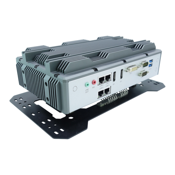
MIL-STD Rugged Computer Version 1.1 SR10B User’s Manual Revision Date: Oct, 07 2016 1.2 Front Panel Components 2 x USB 3.0 (Type A) LED Indicators 2 x DB9 (2 x RS232) Power Button Power Input (9~36V DC in) Swappable 2.5” HDD Tray 1.3 Back Panel Components... -
Page 9: Mechanical Dimensions
MIL-STD Rugged Computer Version 1.1 SR10B User’s Manual Revision Date: Oct, 07 2016 1.4 Mechanical Dimensions WWW.STACKRACK.COM... -
Page 10: Chapter 2: Jumpers And Connectors Locations
MIL-STD Rugged Computer Version 1.1 SR10B User’s Manual Revision Date: Oct, 07 2016 Jumpers and Connectors Locations Chapter 2: This chapter describes the jumpers and connectors on the systems’ motherboard. 2.1 Front Panel Connector Pin Definitions Status Indicators LAN1 LED STATUS... -
Page 11: Com3: Rs232 With 5V/12V Select By Jumper
MIL-STD Rugged Computer Version 1.1 SR10B User’s Manual Revision Date: Oct, 07 2016 COM3: RS232 with 5V/12V select by jumper COM4: RS232 with 5V/12V select by jumper PIN DEFINITION PIN DEFINITION 1 DCD 6 DSR 2 RXD 7 RTS 3 TDX... -
Page 12: Com1: Rs232/422/485 With 5V/12V Selectable (Default Rs232)
MIL-STD Rugged Computer Version 1.1 SR10B User’s Manual Revision Date: Oct, 07 2016 COM1: RS232/422/485 with 5V/12V selectable (Default RS232) COM2: RS232/422/485 with 5V/12V selectable (Default RS232) Pin RS-232 RS-422 Half Duplex RS-485 DCD# DTR# DSR# RTS# CTS# RI# (Define by JP12) RI# (Define by JP12) RI# (Define by JP12) USB3.0 CN18: USB3.0 *2... -
Page 13: Internal Connector
MIL-STD Rugged Computer Version 1.1 SR10B User’s Manual Revision Date: Oct, 07 2016 2.3 Internal Connector MCARD1: Mini PCIE Card Slot<COLAY mSATA> PIN DEFINITION PIN DEFINITION WAKE# 3.3VAUX COEX1 COEX2 1.5V CLKREQ# UIM_PWR UIM_DATA REFCLK- UIM_CLK REFCLK+ UIM_RESET UIM_VPP Reserved... -
Page 14: Chapter 3: Installation
MIL-STD Rugged Computer Version 1.1 SR10B User’s Manual Revision Date: Oct, 07 2016 Chapter 3: Installation This chapter provide users the steps to install the HDD tray and vibration isolation base. 3.1 HDD tray • Loosen the screws and pull out the 2.5” HDD tray. -
Page 15: Vibration Isolation Base
MIL-STD Rugged Computer Version 1.1 SR10B User’s Manual Revision Date: Oct, 07 2016 3.2 Vibration Isolation Base • Let the computer be upside down. • Locate the vibration isolation base on the computer by the screw holes. • Pick 6 screws from the screw package. -
Page 16: Chapter 4: Ami Bios Utility
MIL-STD Rugged Computer Version 1.1 SR10B User’s Manual Revision Date: Oct, 07 2016 Chapter 4: AMI BIOS UTILITY This chapter provides users with detailed descriptions on how to set up a basic system configuration through the AMI BIOS setup utility. -
Page 17: Main Menu
MIL-STD Rugged Computer Version 1.1 SR10B User’s Manual Revision Date: Oct, 07 2016 4.3 Main Menu The Main menu is the screen that first displays when BIOS Setup is entered, unless an error has occurred. You could setup these items on the Main menu: System Language: Choose the system default language. -
Page 18: Advanced Menu
MIL-STD Rugged Computer Version 1.1 SR10B User’s Manual Revision Date: Oct, 07 2016 4.4 Advanced Menu This section allows you to configure and improve your system and allows you to set up some system features according to your preference. WWW.STACKRACK.COM... -
Page 19: Pci Subsystem Settings
MIL-STD Rugged Computer Version 1.1 SR10B User’s Manual Revision Date: Oct, 07 2016 4.4.1 PCI Subsystem Settings PCI, PCI-X and PCI Express settings. PCI Common Settings PCI Latency Timer: Value to be programed into PCI Latency Timer Register. VGA Palette Snoop: Enable or disable VGA Palette Registers Snooping. - Page 20 MIL-STD Rugged Computer Version 1.1 SR10B User’s Manual Revision Date: Oct, 07 2016 Link Training Retry Defines number of retry attempts software will take to retrain the link if previous training attempt was unsuccessful. Link Training Time out (uS) Defines number of Microseconds software will wait before polling “Link training” bit in link status register.
-
Page 21: Acpi Settings
MIL-STD Rugged Computer Version 1.1 SR10B User’s Manual Revision Date: Oct, 07 2016 4.4.2 ACPI Settings System ACPI Parameters. Enable ACPI Auto Configuration Enable/disable BIOS ACPI Auto Configuration. Enable Hibernation Enables or Disables system ability to hibernate (OS/S4 sleep state). This option may be not effective with some OS. -
Page 22: Cpu Configuration
MIL-STD Rugged Computer Version 1.1 SR10B User’s Manual Revision Date: Oct, 07 2016 4.4.3 CPU configuration CPU Configuration Parameters. WWW.STACKRACK.COM... - Page 23 MIL-STD Rugged Computer Version 1.1 SR10B User’s Manual Revision Date: Oct, 07 2016 Hyper-threading Enable for windows XP and Linux(OS optimized for Hyper-Threading Technology) and Disabled for other OS (OS not optimized for Hyper-Threading Technology). When Disabled only one thread per enabled core is enabled.
- Page 24 MIL-STD Rugged Computer Version 1.1 SR10B User’s Manual Revision Date: Oct, 07 2016 Limit CPUID Maximum Disable for Windows XP. Execute Disable Bit XD can prevent certain classes of malicious buffer overflow attecks when combined with a supporting OS. Intel Virtualization Technology When enabled, a VMM can utilize the additional hardware capabilities provided by Vanderpool Technology.
- Page 25 MIL-STD Rugged Computer Version 1.1 SR10B User’s Manual Revision Date: Oct, 07 2016 Energy performance Optimize between performance and power savings. Package power limit lock: When enabled PACKAGE_POWER_LIMIT MSR will be locked and a reset will be required to unlock the register.
- Page 26 MIL-STD Rugged Computer Version 1.1 SR10B User’s Manual Revision Date: Oct, 07 2016 Package C State limit C0/C1, C2, C3, C6, C7, C7s, AUTO LakeTiny Feature Enable/Disable LakeTiny for C state configuration. ACPI CTDP BIOS Enable/Disable ACPI CTDP BIOS support.
-
Page 27: Sata Configuration
MIL-STD Rugged Computer Version 1.1 SR10B User’s Manual Revision Date: Oct, 07 2016 4.4.4 SATA Configuration This section is used to configure the SATA drives. SATA Controller(s) Enable or disable SATA device. SATA Mode Selection Determines how SATA controller(s) operate. The options are: IDE, AHCI, RAID... - Page 28 MIL-STD Rugged Computer Version 1.1 SR10B User’s Manual Revision Date: Oct, 07 2016 Aggressive LPM Support Enable PCH to aggressively enter link power state. SATA Controller Speed Indicates the maximum speed the SATA controllers can support. The options are default, Gen1, Gen2, Gen3.
-
Page 29: Software Feature Mask Configuration
MIL-STD Rugged Computer Version 1.1 SR10B User’s Manual Revision Date: Oct, 07 2016 Software Feature Mask Configuration RADI OROM/RST driver will refer to the SWFW configuration to enable or disable the storage features. RAID0: Enable or disable RAID0 feature. RAID1: Enable or disable RAID1 feature. - Page 30 MIL-STD Rugged Computer Version 1.1 SR10B User’s Manual Revision Date: Oct, 07 2016 Serial ATA Port 2 Port 2: Enable or disable SATA port Hot Plug: Designates this port as Hot Pluggable. External SATA: External SATA support. SATA device type: Identify the SATA port is connected to Solid State Drive or Hard Disk Drive.
-
Page 31: Intel Rapid Start Technology
MIL-STD Rugged Computer Version 1.1 SR10B User’s Manual Revision Date: Oct, 07 2016 4.4.5 Intel Rapid Start Technology Enable or disable Intel Rapid Start Technology 4.4.6 PCH-FW Configuration Configure Management Engine Technology Parameters. MDES BIOS Status Code Enable/Disable MDES BIOS Status Code. -
Page 32: Firmware Update Configuration
MIL-STD Rugged Computer Version 1.1 SR10B User’s Manual Revision Date: Oct, 07 2016 Firmware Update Configuration Configure Management Engine Technology Parameters. Me FW Image Re-Flash: Enable/Disable Me FW Image Re-Flash function. 4.4.7 Intel Anti-Theft Technology Configuration Disabling Intel AT allow user to login to platform. This is strictly for testing only. This does not disable Intel AT services in ME. -
Page 33: Amt Configuration
MIL-STD Rugged Computer Version 1.1 SR10B User’s Manual Revision Date: Oct, 07 2016 4.4.8 AMT Configuration Configure Active Management Technology Parameters. Intel AMT Enable/Disable Intel Active Management Technology BIOS Extension. Note: iAMT H/W is always enabled. This option just controls the BIOS extension execution. If enabled, this requires additional firmware in the SPI device. - Page 34 MIL-STD Rugged Computer Version 1.1 SR10B User’s Manual Revision Date: Oct, 07 2016 Enable/Disable Alert Specification Format. Activate Remote Assistance Process Trigger CIRA boot. USB Configure Enable/Disable USB Configure function. PET Progress User can Enable/Disable PET Events progress to receive PET events or not.
-
Page 35: Usb Configuration
MIL-STD Rugged Computer Version 1.1 SR10B User’s Manual Revision Date: Oct, 07 2016 4.4.9 USB Configuration USB Configuration Parameters. Legacy USB Support Enables legacy USB support. AUTO option disables legacy support if no USB devices are connected. DISABLE option will keep USB devices available only for EFI applications. -
Page 36: It8786 Super Io Configuration
MIL-STD Rugged Computer Version 1.1 SR10B User’s Manual Revision Date: Oct, 07 2016 USB hardware delays and time-outs: USB transfer time-out: The time-out value for Control, Bulk, and Interrupt transfers. The options are 1 sec, 5 sec, 10 sec, 20 sec. -
Page 37: Serial Port 4 Configuration
MIL-STD Rugged Computer Version 1.1 SR10B User’s Manual Revision Date: Oct, 07 2016 Serial Port 4 Configuration Set Parameters of Serial Port 3 (COMD). Serial Port: Enable or Disable Serial Port (COM). Device Settings: IO=2E8h, IRQ=7 Change Settings: Select an optimal setting for Super IO device. -
Page 38: It8786 Hw Monitor
MIL-STD Rugged Computer Version 1.1 SR10B User’s Manual Revision Date: Oct, 07 2016 4.4.11 IT8786 HW Monitor Monitor hardware status. 4.4.12 Serial Port Console Redirection Console Redirection Console Redirection Enable or Disable. Console Redirection Setting The Settings specify how the host computer and the remote computer will exchange data. Both computers... -
Page 39: Network Stack
MIL-STD Rugged Computer Version 1.1 SR10B User’s Manual Revision Date: Oct, 07 2016 should have the same or compatible setting. Out-of-Band Mgmt Port: Microsoft Windows Emergency Management Service allows for remote management of a Windows Server OS through a serial port. The options are COM0 (Disabled), COM1(Pci Bus0, Dev0, Func0) (Disabled) Terminal Type: VT-UTF8 is the preferred terminal type for out-of-band management. -
Page 40: Intel I210-It Gigabit Network Connection
MIL-STD Rugged Computer Version 1.1 SR10B User’s Manual Revision Date: Oct, 07 2016 4.4.14 Intel I210-IT Gigabit Network Connection Configure Gigabit Ethernet device parameters. PORT CONFIGURATION MENU NIC Configuration: Configure Boot Protocol, wake on LAN, Link Speed, and VLAN. Blink LEDs: Identify the physical network port by blinking the associated LED. -
Page 41: Chipset
MIL-STD Rugged Computer Version 1.1 SR10B User’s Manual Revision Date: Oct, 07 2016 4.5 Chipset This section gives you functions to configure the system based on the specific features of the chipset. The chipset manages bus speeds and access to system memory resources. - Page 42 MIL-STD Rugged Computer Version 1.1 SR10B User’s Manual Revision Date: Oct, 07 2016 PCI Express Root Port1 PCI Express Root Port1 setting. Only enabled ASPM Support: Set the ASPM Level: Force L0s – Force all links to L0s State: AUTO – BIOS auto configure : DISABLE –...
- Page 43 MIL-STD Rugged Computer Version 1.1 SR10B User’s Manual Revision Date: Oct, 07 2016 PCI Express Root Port2 control the PCI Express Root port, the options are enabled/disabled. ASPM Support: Set the ASPM Level: Force L0s – Force all links to L0s State: AUTO – BIOS auto configure: DISABLE –...
- Page 44 MIL-STD Rugged Computer Version 1.1 SR10B User’s Manual Revision Date: Oct, 07 2016 PCI Express Root Port3 control the PCI Express Root port, the options are enabled/disabled ASPM Support: Set the ASPM Level: Force L0s – Force all links to L0s State: AUTO – BIOS auto configure: DISABLE –...
- Page 45 MIL-STD Rugged Computer Version 1.1 SR10B User’s Manual Revision Date: Oct, 07 2016 PCI Express Root Port5: control the PCI Express Root port, the options are enabled/disabled ASPM Support: Set the ASPM Level: Force L0s – Force all links to L0s State: AUTO – BIOS auto configure: DISABLE –...
- Page 46 MIL-STD Rugged Computer Version 1.1 SR10B User’s Manual Revision Date: Oct, 07 2016 PCI Express Root Port6 control the PCI Express Root port, the options are enabled/disabled ASPM Support: Set the ASPM Level: Force L0s – Force all links to L0s State: AUTO – BIOS auto configure: DISABLE –...
- Page 47 MIL-STD Rugged Computer Version 1.1 SR10B User’s Manual Revision Date: Oct, 07 2016 PCI Express Root Port7 control the PCI Express Root port, the options are enabled/disabled ASPM Support: Set the ASPM Level: Force L0s – Force all links to L0s State: AUTO – BIOS auto configure: DISABLE –...
-
Page 48: Usb Configuration
MIL-STD Rugged Computer Version 1.1 SR10B User’s Manual Revision Date: Oct, 07 2016 PCI Express Root Port8 control the PCI Express Root port, the options are enabled/disabled ASPM Support: Set the ASPM Level: Force L0s – Force all links to L0s State: AUTO – BIOS auto configure: DISABLE –... - Page 49 MIL-STD Rugged Computer Version 1.1 SR10B User’s Manual Revision Date: Oct, 07 2016 Board Capability Board Capability-SUS_PWR_DN_ACK->Send Disabled to PCH, DeepSx->Show DeepSx Policies. GP27 Wake From DeepSx Wake from DeepSx by the assertion of GP27 pin. PCIE From DeepSx Wake Wake from DeepSx by the assertion of PCIE.
-
Page 50: Watch Dog Function Select
MIL-STD Rugged Computer Version 1.1 SR10B User’s Manual Revision Date: Oct, 07 2016 Watch Dog Function select WWW.STACKRACK.COM... -
Page 51: System Agent Sa
MIL-STD Rugged Computer Version 1.1 SR10B User’s Manual Revision Date: Oct, 07 2016 4.5.2 System AGENT SA VT-d Check to enable VT-d function on MCH. Graphics Configuration Graphics Turbo IMON Current: Graphics turbo IMON current values supported (14-31). Primary Display: select which of AUTO/IGFX/PEG/SG graphics device should be primary display or select SG for switchable GFX Primary PEG: Select Auto/PEG1/PEG2 Graphics device should be Primary PEG. -
Page 52: Memory Configuration
MIL-STD Rugged Computer Version 1.1 SR10B User’s Manual Revision Date: Oct, 07 2016 LCD Control Primary IGFX Boot Display: Select the Video Device which will be activated during POST. This has no effect if external graphics present. Secondary boot display selection will appear based on your selection. -
Page 53: Boot
MIL-STD Rugged Computer Version 1.1 SR10B User’s Manual Revision Date: Oct, 07 2016 4.6 Boot This section is used to configure the boot features. Setup Prompt Timeout Number of seconds to wait for setup activation key. 65535(0xFFFF) means indefinite waiting. - Page 54 MIL-STD Rugged Computer Version 1.1 SR10B User’s Manual Revision Date: Oct, 07 2016 INT19 Trap Response: BIOS reaction on INT19 trapping by option ROM: IMMEDIATE-execute the trap right away; POSTPONES-execute the trap during legacy boot. CSM Parameters OpROM execution, boot options filter, etc.
-
Page 55: Security
MIL-STD Rugged Computer Version 1.1 SR10B User’s Manual Revision Date: Oct, 07 2016 4.7 Security Use the Security Menu to establish system passwords Administrator Password Set Administartor Password. User Password Set User Password. HDD Security Configuration Set HDD Password. WWW.STACKRACK.COM... -
Page 56: Save And Exit
MIL-STD Rugged Computer Version 1.1 SR10B User’s Manual Revision Date: Oct, 07 2016 4.8 Save and Exit This screen provides functions for handling changes made to the BIOS settings and the exiting of the Setup program. Save Changes and Exit Exit system setup after saving the changes.
Need help?
Do you have a question about the SR10B and is the answer not in the manual?
Questions and answers