
Related Manuals for Stackrack SR700


Summary of Contents for Stackrack SR700
- Page 1 MIL-STD Rugged Computer Version 1.0 User’s Manual Revision Date: NOV. 23, 2016 SR700 MIL-STD Rugged Computer User’s Manual WWW.STACKRACK.COM...
-
Page 2: Safety Information
All rights reserved. No part of this publication may be reproduced in any form or by any means, without prior written permission from the publisher. All trademarks are the properties of the respective owners. All product specifications are subject to change without prior notice WWW.STACKRACK.COM... -
Page 3: Revision History
Draft Version V1.0 2016/11/23 Initial release Packing list □ SR700 MIL-STD Rugged Computer □ XR-DIMM up to 8 GB RAM optional □ NVIDIA GTX950M MXM Graphic Card Accessories Kit □ M12 4 PIN DC Connector x 1pcs □ CD (Driver + User’s Manual) □... -
Page 4: Table Of Contents
3.4.4 SATA Configuration ..........................21 Software Feature Mask Configuration ..................... 23 3.4.5 Intel Rapid Start Technology ......................... 25 3.4.6 PCH-FW Configuration .......................... 25 Firmware Update Configuration ....................... 26 3.4.7 Intel Anti-Theft Technology Configuration ................... 26 3.4.8 AMT Configuration ..........................27 WWW.STACKRACK.COM... - Page 5 3.5.2 System AGENT SA ..........................43 Graphics Configuration ..........................44 LCD Control ............................44 Memory Configuration..........................44 GT- Power Management Control ......................44 3.6 B ................................45 CSM16 Parameters ............................ 46 3.7 S ................................46 ECURITY 3.8 S ..............................47 AVE AND WWW.STACKRACK.COM...
-
Page 6: Chapter 1: Product Introduction
Method 501.5, Procedure II (Operation/High Temperature) Method 502.5, Procedure I (Storage/Low Temperature) Method 502.5, Procedure II (Operation/Low Temperature) Method 503.5, Procedure I (Temperature shock) CE and FCC compliance Green Product RoHS, WEEE compliance *Specifications are subject to change without notice* WWW.STACKRACK.COM... -
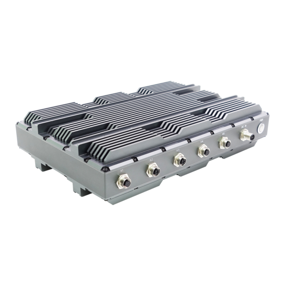
Page 7: Front Panel Components
Revision Date: NOV. 23, 2016 1.2 Front Panel Components DC IN 1 x DC input 2 x USB2.0 1 x GbE LAN 1 x GbE LAN 1 x VGA 1 x RS232, 1 x RS485 Power Button with LED backlight WWW.STACKRACK.COM... -
Page 8: Mechanical Dimensions
MIL-STD Rugged Computer Version 1.0 User’s Manual Revision Date: NOV. 23, 2016 1.3 Mechanical Dimensions WWW.STACKRACK.COM... -
Page 9: Chapter 2: Jumpers And Connectors
This chapter describes the jumpers and connectors on the systems’ motherboard. 2.1 Front Panel Connector Pin Definitions DC IN Phoenix Contact [1424132] PIN DEFINITION X1: USB Phoenix Contact [1441817] USB2.0 PIN DEFINITION USB1 Gound USB2 Gound X2: GbE LAN X3: GbE LAN Phoenix Contact [1441817] PIN DEFINITION WWW.STACKRACK.COM... -
Page 10: X4: Vga
Revision Date: NOV. 23, 2016 X4: VGA Phoenix Contact [1441833] PIN DEFINITION R Ground GREEN G Ground BLUE B Ground H-Sync V-Sync DDC DATA DDC LOCK X5: COM Phoenix Contact [1441833] PIN DEFINITION COM1 RS232 RXD(D+) COM2 RS485 DCD(D-) WWW.STACKRACK.COM... -
Page 11: Internal Connector And Jumper Setting
PIN DEFINITION PIN DEFINITION WAKE# 3.3VAUX COEX1 COEX2 1.5V CLKREQ# UIM_PWR UIM_DATA REFCLK- UIM_CLK REFCLK+ UIM_RESET UIM_VPP Reserved Reserved W_Disable# PERST# PERn0 +3.3Vaux PERp0 1.5V SMB_CLK PETn0 SMB_DATA PETp0 USB_D- USB_D+ +3.3VAUX +3.3VAUX LED_WWAN# LED_WLAN# Reserved LED_WPAN# Reserved 1.5V Reserved Reserved 3.3VAUX WWW.STACKRACK.COM... -
Page 12: Chapter 3: Ami Bios Utility
The <F10> key saves any changes made and exits the BIOS setup utility. The <Esc> key discards any changes made and exits the BIOS setup utility. Enter The <Enter> key displays a sub-screen or changes a selected or highlighted option in each menu. WWW.STACKRACK.COM... -
Page 13: Main Menu
System Language: Choose the system default language. System Date: Set the date. Use Tab to switch between date elements. System Time: Set the time. Use Tab to switch between time elements. Access Level Displays the access level of the current user in the BIOS. WWW.STACKRACK.COM... -
Page 14: Advanced Menu
MIL-STD Rugged Computer Version 1.0 User’s Manual Revision Date: NOV. 23, 2016 3.4 Advanced Menu This section allows you to configure and improve your system and allows you to set up some system features according to your preference. WWW.STACKRACK.COM... -
Page 15: Pci Subsystem Settings
ASPM Support: Set the ASPM level: Force L0s - Force all links to L0s state: AUTO - BIOS auto configure: DISABLE- Disables ASPM. WARNING: Enabling ASPM may cause some PCI-E devices to fail. Extended Synch: If ENBLED allows generation of extended synchronization patterns. WWW.STACKRACK.COM... -
Page 16: Acpi Settings
Warning: Enabling this may cause issues with other hardware after S3 resume. 3.4.2 ACPI Settings System ACPI Parameters. Enable ACPI Auto Configuration Enable/disable BIOS ACPI Auto Configuration. Enable Hibernation Enables or Disables system ability to hibernate (OS/S4 sleep state). This option may be not effective with some OS. WWW.STACKRACK.COM... -
Page 17: Cpu Configuration
Select ACPI sleep state the system will enter when the suspend button is pressed. Lock Legacy Resources Enable or disable lock of legacy resource. S3 Video Repost Enable or disable S3 Video Repost. 3.4.3 CPU configuration CPU Configuration Parameters. WWW.STACKRACK.COM... - Page 18 MIL-STD Rugged Computer Version 1.0 User’s Manual Revision Date: NOV. 23, 2016 WWW.STACKRACK.COM...
- Page 19 Intel Virtualization Technology When enabled, a VMM can utilize the additional hardware capabilities provided by Vanderpool Technology. Hardware Prefetcher Enable the mid level cache(L2) streamer prefetcher. Adjacent Cache Line Prefetcher Enable the mid level cache(L2) prefetching of adjacent cache lines. WWW.STACKRACK.COM...
- Page 20 4-Core Ratio Limit: This limit is for 4 cores active. 0 means using the factory-configured value. VR Current value lock Locks VR Current value from further writes until a reset. VR Current value Voltage regulator current limit. 0 means AUTO. WWW.STACKRACK.COM...
- Page 21 Allows reconfiguration of TDP levels base on current power and thermal delivery capabilities of the system. Configure TDP lock Lock the Config TDP control register. TCC activation offset Offset from the factory TCC activation temperature. Intel TXT(LT) Support Only Disable ACPI T state Enable/Disable ACPI T state support. WWW.STACKRACK.COM...
-
Page 22: Sata Configuration
Lock CPU debug interface setting. IOUT OFFSET Sign 0 positive offset. 1 negative offset. IOUT OFFSET VR IOUT OFFSET configuration 0~625. IOUT SLOPE VR IOUT SLOPE configuration range 0~1023. 3.4.4 SATA Configuration This section is used to configure the SATA drives. WWW.STACKRACK.COM... - Page 23 Determines how SATA controller(s) operate. The options are: IDE, AHCI, RAID SATA Test Selection Enable or disable Test Mode Aggressive LPM Support Enable PCH to aggressively enter link power state. SATA Controller Speed Indicates the maximum speed the SATA controllers can support. The options are default, Gen1, Gen2, Gen3. WWW.STACKRACK.COM...
-
Page 24: Software Feature Mask Configuration
External SATA: External SATA support. SATA device type: Identify the SATA port is connected to Solid State Drive or Hard Disk Drive. Spin Up Device: On an edge detec from 0 to 1, the PCH starts a COMRESET initialization sequence to the device. WWW.STACKRACK.COM... - Page 25 External SATA: External SATA support. SATA device type: Identify the SATA port is connected to Solid State Drive or Hard Disk Drive. Spin Up Device: On an edge detec from 0 to 1, the PCH starts a COMRESET initialization sequence to the device. WWW.STACKRACK.COM...
-
Page 26: Intel Rapid Start Technology
MIL-STD Rugged Computer Version 1.0 User’s Manual Revision Date: NOV. 23, 2016 3.4.5 Intel Rapid Start Technology Enable or disable Intel Rapid Start Technology 3.4.6 PCH-FW Configuration Configure Management Engine Technology Parameters. MDES BIOS Status Code Enable/Disable MDES BIOS Status Code. WWW.STACKRACK.COM... -
Page 27: Firmware Update Configuration
Disabling Intel AT allow user to login to platform. This is strictly for testing only. This does not disable Intel AT services in ME. Intel Anti-Theft Technology Enable/Disable Intel AT in BIOS for testing. On Enter Intel AT Suspend Mode Only Disabled WWW.STACKRACK.COM... -
Page 28: Amt Configuration
OEMFlag Bit 6: Hide Un-Configure ME without password Configuration prompt. MEBx Debug Message Output OEMFlag Bit 14: Enable MEBx debug message output. Un-Configure ME OEMFlag Bit 15: Un-Configure ME without password. Amt Wait Timer Set Timer to wait before sending ASF_GET_BOOT_OPTIONS. WWW.STACKRACK.COM... - Page 29 Set ME to Soft Temporary Disabled. Enable/Disable Alert Specification Format. Activate Remote Assistance Process Trigger CIRA boot. USB Configure Enable/Disable USB Configure function. PET Progress User can Enable/Disable PET Events progress to receive PET events or not. WatchDog Enable/Disable WatchDog Timer. WWW.STACKRACK.COM...
-
Page 30: Usb Configuration
This is a workaround for OSes without XHCI hand-off support. The XHCI ownership change should be claimed by XHCI driver. EHCI Hand-off This is a workaround for OSes without EHCI hand-off support. The EHCI ownership change should be claimed by EHCI driver. USB Mass Storage Driver Support Enable/Disable USB Mass Storage Driver Support. WWW.STACKRACK.COM... -
Page 31: It8786 Super Io Configuration
Change Settings: Select an optimal setting for Super IO device. Serial Port 2 Configuration Set Parameters of Serial Port 1 (COMB). Serial Port: Enable or Disable Serial Port (COM). Device Settings: IO=2F8h, IRQ=3 Change Settings: Select an optimal setting for Super IO device. WWW.STACKRACK.COM... -
Page 32: Serial Port 3 Configuration
Change Settings: Select an optimal setting for Super IO device. Serial Port 6 Configuration Set Parameters of Serial Port 5 (COMF). Serial Port: Enable or Disable Serial Port (COM). Device Settings: IO=2E0h, IRQ=7 Change Settings: Select an optimal setting for Super IO device. WWW.STACKRACK.COM... -
Page 33: It8786 Hw Monitor
MIL-STD Rugged Computer Version 1.0 User’s Manual Revision Date: NOV. 23, 2016 3.4.11 IT8786 HW Monitor Monitor hardware status. 3.4.12 Serial Port Console Redirection Console Redirection Console Redirection Enable or Disable. WWW.STACKRACK.COM... -
Page 34: Console Redirection Setting
“star” signal can be sent to re-start the flow. Hardware flow control uses two wires to send start/stop signals. The options are None, Hardware RTS/CTS, Software Xon/xoff Data bits: 8 Parity: None Stop bits: 1 3.4.13 Network Stack Network stack settings Network Stack Enable/Disable UEFI network stack WWW.STACKRACK.COM... -
Page 35: Intel I210 Gigabit Network Connection
NIC Configuration: Configure Boot Protocol, wake on LAN, Link Speed, and VLAN. Blink LEDs: Identify the physical network port by blinking the associated LED. PORT CONFIGURATION INFORMATION Link Status: Link Status. Virtual MAC Address: Programmatically assignable MAC address for port. WWW.STACKRACK.COM... -
Page 36: Chipset
Revision Date: NOV. 23, 2016 3.5 Chipset This section gives you functions to configure the system based on the specific features of the chipset. The chipset manages bus speeds and access to system memory resources. 3.5.1 PCH IO configuration WWW.STACKRACK.COM... -
Page 37: Pci Express Configuration
Reserved I/O: Reserved I/O (4K/8K/12K/16K/…/48K) Range for this Root Bridge. PCIE LTR: PCIE Latency Reporting Enable/Disable. PCIE LTR Lock: PCIE LTR configuration lock. Snoop Latency Ocerride: Snoop Latency Ocerride for PCH PCIE. Non Snoop Latency Ocerride: Non Snoop Latency Ocerride for PCH PCIE. WWW.STACKRACK.COM... -
Page 38: Pci Express Root Port2
Reserved I/O: Reserved I/O (4K/8K/12K/16K/…/48K) Range for this Root Bridge. PCIE LTR: PCIE Latency Reporting Enable/Disable. PCIE LTR Lock: PCIE LTR configuration lock. Snoop Latency Ocerride: Snoop Latency Ocerride for PCH PCIE. Non Snoop Latency Ocerride: Non Snoop Latency Ocerride for PCH PCIE. WWW.STACKRACK.COM... -
Page 39: Pci Express Root Port3
Reserved I/O: Reserved I/O (4K/8K/12K/16K/…/48K) Range for this Root Bridge. PCIE LTR: PCIE Latency Reporting Enable/Disable. PCIE LTR Lock: PCIE LTR Configuration Lock. Snoop Latency Ocerride: Snoop Latency Ocerride for PCH PCIE. Non Snoop Latency Ocerride: Non Snoop Latency Ocerride for PCH PCIE. WWW.STACKRACK.COM... -
Page 40: Pci Port 4 Is Assigned To Lan
Reserved I/O: Reserved I/O (4K/8K/12K/16K/…/48K) Range for this Root Bridge. PCIE LTR: PCIE Latency Reporting Enable/Disable. PCIE LTR Lock: PCIE LTR Configuration Lock. Snoop Latency Ocerride: Snoop Latency Ocerride for PCH PCIE. Non Snoop Latency Ocerride: Non Snoop Latency Ocerride for PCH PCIE. WWW.STACKRACK.COM... -
Page 41: Pci Express Root Port6
Reserved I/O: Reserved I/O (4K/8K/12K/16K/…/48K) Range for this Root Bridge. PCIE LTR: PCIE Latency Reporting Enable/Disable. PCIE LTR Lock: PCIE LTR Configuration Lock. Snoop Latency Ocerride: Snoop Latency Ocerride for PCH PCIE. Non Snoop Latency Ocerride: Non Snoop Latency Ocerride for PCH PCIE. WWW.STACKRACK.COM... -
Page 42: Pci Express Root Port7
Reserved I/O: Reserved I/O (4K/8K/12K/16K/…/48K) Range for this Root Bridge. PCIE LTR: PCIE Latency Reporting Enable/Disable. PCIE LTR Lock: PCIE LTR Configuration Lock. Snoop Latency Ocerride: Snoop Latency Ocerride for PCH PCIE. Non Snoop Latency Ocerride: Non Snoop Latency Ocerride for PCH PCIE. WWW.STACKRACK.COM... -
Page 43: Pci Express Root Port8
Enable or disable onboard NIC. Wake on LAN: Enable or disable integrated LAN to wake the system. (The Wake On LAN cannot be disabled if ME is on at Sx state.) SLP_LAN# Low on DC Power: Enable/Disable SLP_LAN# Low on DC Power. WWW.STACKRACK.COM... -
Page 44: System Agent Sa
Configure Serial IRQ Mode. SLP_S4 Assertion Width Select a minimum assertion width of the SLP_S4# signal. Port 80h Redirection Control where the Port 80h cycles are sent. 3.5.2 System AGENT SA VT-d Check to enable VT-d function on MCH. WWW.STACKRACK.COM... -
Page 45: Graphics Configuration
Max TOLUD: Maximum Value of TOLUD. Dynamic assignment would adjust TOLUD automatically based on largest MMIO length of installed graphic controller. GT- Power Management Control RC6 (render standby): check to enable render standby support. GT OverClocking Support: enable or disable GT overclocking support WWW.STACKRACK.COM... -
Page 46: Boot
Enables or disables boot with initialization of a minimal set of devices required to launch active boot option. Has no effect for BBS boot options. Boot option priorities Boot Option #1: Sets the system boot order. Hard Drive BBS Priorities Set the order of the legacy devices in this group WWW.STACKRACK.COM... -
Page 47: Csm16 Parameters
POSTPONES-execute the trap during legacy boot. CSM Parameters OpROM execution, boot options filter, etc. 3.7 Security Use the Security Menu to establish system passwords Administrator Password Set Administartor Password. User Password Set User Password. HDD Security Configuration Set HDD Password. WWW.STACKRACK.COM... -
Page 48: Save And Exit
Save Changes: Save Changes done so far to any of the setup options. Discard Changes: Discard Changes done so far to any of the setup options. Restore Defaults Restore/Load Default values for all the setup options. Save as User Defaults Save the changes done so far as User Defaults. WWW.STACKRACK.COM... - Page 49 User’s Manual Revision Date: NOV. 23, 2016 Restore user Defaults Restore the User Defaults to all the setup options. Launch EFI Shell from filesystem device Attempts to launch EFI Shell application (Shellx64.efi) from one of the available filesystem devices. WWW.STACKRACK.COM...
Need help?
Do you have a question about the SR700 and is the answer not in the manual?
Questions and answers