Advertisement
Quick Links
Advertisement

Related Manuals for HuddleCamHD 10X-G3


Summary of Contents for HuddleCamHD 10X-G3
- Page 1 HuddleCamHD 10x (Gen 3) USB 3.0 PTZ CAMERA INSTALLATION & OPERATION MANUAL...
- Page 2 Precautions…………………………………………………………………………………………. Safety Tips……………………………………………………………………………………………. Please read this manual carefully before using the camera. Avoid damage from stress, violent vibration or liquid intrusion during transportation, storage or installation. Take care of the camera during installation to prevent damage to the camera case, ports, lens or PTZ mechanism.
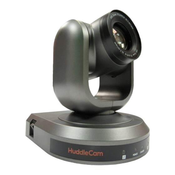
- Page 3 Physical Description……………………………………………………………………… Front View………………………………………………………………………………… Lens IR Receiver To receive IR remote controller signal. Power LED Blue LED lights when unit is powered and on. Stand by LED Orange LED lights when unit is powered and in standby. IR Receiver To receive IR remote controller signal. Ver 1.1 6/16...
- Page 4 2. Rear View…………………………………………………………………………………………. USB 3.0 Interface For connection to PC USB 3.0 port (also compatible with USB 2.0 port and driver). IR Selective Switch When using only one remote to control more than one camera, this switch will assign a unique ID to each camera. VISCA IN Port For hard wired remote control from a 3 party PC, joystick, etc...
- Page 5 Bottom View…………………………………………………………………………………. 1. Dip-Switch Used for selecting baud rate and the remote signal output switch. 2. Tripod Will accept 1/4-20 bolt from 3 party tripod, wall or ceiling mount. Ver 1.1 6/16...
- Page 6 4. Dip-Switch Settings………………………………………………………………………….. Note: When changing Dip-Switch settings, make all changes with camera powered off. Dip-Switch 1 - (To set communication baud rate). Dip-Switch 2 - (To set control protocol). Dip-Switch 3 - (Set only for firmware upgrading). Dip Switch 4 & 5 - (To set camera’s RS232/RS485 ID number – for daisy chain wired control).
- Page 7 Cable Connection Info………………………………………………………………………… VISCA RS-232C - IN Reference……………………………………………………………… VISCA RS-232C - Out Reference…………………………………………………………… Note: RS-485 connection (in/out) is only made to the VISCA Out port Ver 1.1 6/16...
- Page 8 OSD MENU…………………………………………………………………………………………….. On Screen Display Menu - Use the OSD menu to access and change the camera’s settings. Note: You cannot manually move the camera (pan/tilt) when the OSD menu is visible on the screen. The Dome OSD Menu is as follows: ...
- Page 9 Frame Default Value: 60Hz o Set Refresh Rate Range = 50Hz or 60 Hz Preset Freeze Default Value: Off (Provides automatic temporary freeze frame when switching between presets) Range = On – Off The Lens OSD Menu is as follows: ...
- Page 10 BRIGHT Default Value: 23 o Set Brightness 0 - 31 Ver 1.1 6/16...
-
Page 11: Ir Remote Controller
IR Remote Controller (Note: Some buttons do not operate for all camera models) Reset: Restarts the camera and restores it to Factory Default settings. (Note: Will delete all memory). Camera Selection Select Camera ID: 1, 2 or 3 Preset Positions 1-9: Preset Positions Set: Setting Preset Position Clear: Clear Preset Position... - Page 12 Pan/Tilt Function Zone L-Limit: Set left boundary limit scanning position Scan: Enable Boundary Scanning (Auto Panning) R-Limit: Set right boundary limit scanning position Home: Go to camera’s Home position Tour: Enable automatic patrol tour of presets Rev: Enable image flip for ceiling mounting Connection Instructions………………………………………………………………………...
- Page 13 Installation Instructions……………………………………………………………………… Desktop Installation……………………………………………………………………………… When using the HuddleCam on a desk, Make sure that it will stand level. If you want to use the camera on an incline, make sure the angle is less than 15 degrees to ensure that the camera’s pan and tilt mechanism operates normally. Tripod Installation…………………………………………………………………………………...
- Page 14 Ceiling Mount………………………………………………………………………………………… Step 1: Ceiling For hard ceilings Use the supplied plastic anchors and screws to fix the ceiling bracket to the ceiling. For acoustic tile ceilings cut a piece of plywood 12” x 23.75” to use Ceiling as a tile bridge above the ceiling tile. Use the supplied screws (without plastic anchors) to fix the ceiling bracket to the plywood, Bracket sandwiching the ceiling tile in between.
- Page 15 Troubleshooting………….………………………………………………………………………… Problem Cause Resolution There is no power to the Power adapter is Check the connections camera. disconnected from mains between the camera, or from camera. power adapter and mains. If anything is disconnected, reconnect Power switch is set to Set the power switch to OFF.
- Page 16 USB 3.0 camera connectivity. HuddleCam Cameras All HuddleCamHD cameras utilize the UVC (USB Video Class) drivers that are built into Windows, Mac OS and Linux to stream HD video to your device via your device’s USB port (USB 2.0 or USB 3.0 depending upon HuddleCam model).
- Page 17 In this example, you can see the HuddleCam model in use connected as a fully functional USB 3.0 device (HuddleCamHD) as well as a USB 2.0 device with limited functionality (USB2.0 Camera). If your device has not connected to or has not recognized the HuddleCam as an imaging device (in which case, you may see a new “unknown device”, “Westbridge”...
- Page 18 Similarly, you can see a connected device in System Information on a MAC. See screenshot below: In this example, you can see the HuddleCam model in use connected as a fully functional USB 3.0 device “HuddleCamHD” as well as a “USB2.0 camera” with limited functionality (USB2.0 camera). Ver 1.1 6/16...
- Page 19 Specs…………………………………………………………………………………………….. Model Number: HC10X-xx-G3 (xx=GY Gray Color, xx=WH White Color) Camera & Lens Video CMOS Sensor 1/2.8” CMOS 2.1 Mega Pixel Frame Rate 30fps 1920 x 1080p, 30fps 1280 x 720p Lens Zoom 10X Optical Zoom, f=4.7-47mm ...
- Page 20 Appendices………………………………………………………………………………………….. Appendix 1 VISCA Command List (1/2) Command Set Command Command Packet Comments AddressSet Broadcast 88 30 01 FF Address setting IF_Clear Broadcast 88 01 00 01 FF I/F Clear CommandCancel 8x 2p FF p: Socket No.(=1or2) CAM_Power 8x 01 04 00 02 FF Power ON/OFF 8x 01 04 00 03 FF Zoom Control...
- Page 21 CAM_Backlight 8x 01 04 33 02 FF Back Light Compensation ON/OFF 8x 01 04 33 03 FF CAM_Memory Reset 8x 01 04 3F 00 0p FF p: Memory Number (=1 to 3F) Corresponds to 1 to 9 on the Remote 8x 01 04 3F 01 0p FF Commander.
- Page 22 VideoSystem SET 8x 01 06 35 00 0p FF Video format Output connetor 1920×1080p/30 DVI-D 1920×1080i/60 HD-SDI 1280×720p/60 1920×1080p/25 VISCA Command List (2/2) Command Set Command Command Packet Comments 1920×1080i/50 1280×720p/50 1920×1080p/24 IR_Receive 8x 01 06 08 02 FF IR(remote commander) receive ON/OFF 8x 01 06 08 03 FF Color system 8x 01 7E 01 03 00 00 FF...
- Page 23 Appendix 2 VISCA Inquiry List (1/1) Inquiry Command Command Inquiry Packet Comments Packet CAM_PowerInq 8x 09 04 00 FF y0 50 02 FF y0 50 03 FF Off (Standby) y0 50 04 FF Internal power circuit error CAM_ZoomPosInq 8x 09 04 47 FF y0 50 0p 0q 0r 0s FF pqrs: Zoom Position CAM_FocusModeInq...
- Page 24 Appendix 3 Special Preset Commands Special Preset Call Functions: Call these presets using VISCA to execute the commands Preset No. Function Enable Stand-by Status Display Self-test (Camera Info) menu OSD Flip Image Vertically (On/Off Toggle) Display Dome OSD Menu Set Left Pan Limit for Pan Scanning Set Right Pan Limit for Pan Scanning Restart Camera with Default Settings Display Lens OSD Menu...
Need help?
Do you have a question about the 10X-G3 and is the answer not in the manual?
Questions and answers