Table of Contents
Advertisement
Quick Links
Advertisement
Table of Contents

Related Manuals for Pentax R-2500NS Series


Summary of Contents for Pentax R-2500NS Series
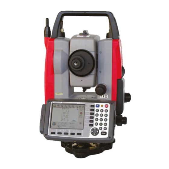
- Page 1 TOTAL STATION R-2500NS SERIES R-2501N R-2502N R-2503N R-2505N INSTRUCTION MANUAL Power Topo Lite TI Asahi Co.,Ltd. International Sales Department 4-3-4 Ueno Iwatsuki-Ku,Saitama-Si Saitama,339-0073 Japan Tel, +81-48-793-0118 Fax, +81-48-793-0128 E-mail : international@tiasahi.com...
-
Page 2: Table Of Contents
CONTENTS GENERAL Contents Exemption clause Copyright Display and Keyboard Operation Key Function Key Display combination of MODE A or MODE B Alphanumeric Input 1. INTRODUCTION 1.1 Introduction 1.2 Before using the PowerTopoLite manual 2. ACCESSING POWERTOPOLITE 2.1 How to access PowerTopoLite 2.2 Allocation of each PowerTopoLite Function key 2.3 Typical Function keys of PowerTopoLite 3. - Page 3 4.8 Offset 4.9 Station setup [By Rectangular & Polar Coordinates] 4.10 Station Orientation 4.11 Function of MEASURE screen 4.12 IH Measurement 5. VIEW AND EDIT 5.1 Graphical View 5.2 Create the Rectangular Point 5.3 Edit the Data 5.4 Point Code List 5.4.1 Point Code 5.4.2 Point Code Create 5.4.3 Point Code Edit...
- Page 4 10. RDM (Remote Distance Measurement) 10.1 PH input 10.2 Reference point - Target distance 10.3 Target- Target distance 10.4 New Reference point selection 11. TRAVERSE 11.1 Start point measuring 11.2 Corner point measuring 11.3 Calculation 12. ROAD DESIGN 12.1 BP, IP, EP input 12.2 Road parameter and pitch input 12.3 IP confirm 12.4 Calculation...
-
Page 5: Exemption Clause
Before using this product, be sure that you have thoroughly read and understood this instruction manual to ensure proper operation. After reading this manual, be sure to keep in a convenient place for easy reference. Exemption clause 1) TI Asahi Co.,Ltd. (TIA) shall not be liable for damage caused by Acts of God, fire, alteration or servicing by unauthorized parties, accident, negligence, misuse, abnormal operating conditions. -
Page 6: Display And Keyboard
DISPLAY AND KEYBOARD • Basic display and keyboard of R-2500NS series are described below, and the function keys of PowerTopoLite are described in “2. ACCESSING POWERTOPOLITE”. Alphanumeric and +/- key Enter key Laser plummet and Power supply key Function key... -
Page 7: Function Key
FUNCTION KEY [ ▽ ] Moves the cursor to the left. [ ▽ ] Moves the cursor to the right. [ ▽ ] Moves the cursor up. [ ▽ ] Moves the cursor down. [ △ ] Goes back five items on the screen. [ ▽... -
Page 8: Display Combination Of Mode A Or Mode B
Display combination of MODE A or MODE B Function MODE A MODE B MEAS S.FUNC TARGET ANG SET 0 SET HOLD DISP CORR MODE MODE • Mode A or Mode B is switched by pressing [F5] [MODE]. ALPHANUMERIC INPUT The point name etc. is input by the alphanumeric keys as following. Letter under key Letter &... -
Page 9: Introduction
PENTAX total station R-2500NS series. PowerTopoLite is developed based on PowerTopo, which is known as a versatile on-board software for PENTAX ATS total station series. The optimum combination of PowerTopoLite and R-2500NS hardware makes PowerTopoLite an easy and useful fieldwork tool. -
Page 10: Before Using The Powertopolite Manual
1.2 Before using the PowerTopoLite manual • Memories in the instrument The R-2500NS series incorporates not only the PowerTopoLite surveying programs as the Special function but also File manager and Data transfer programs. The internal memory of the instrument can store a maximum of 60000 points data •... - Page 11 • IH and PH IH stands for “Instrument Height” and PH stands for “Prism Height”. • The PowerTopoLite manual mainly describes the R-2500NS special functions, and the basic operations are described in the (basic) R-2500NS manual. Therefore, refer to the R-2500NS basic manual regarding the R-2500NS general instrument operations.
-
Page 12: Accessing Powertopolite
2. ACCESSING POWERTOPOLITE 2.1 How to access PowerTopoLite To access the R-2500NS Special Functions of the PowerTopoLite, perform the following procedures. Press the [POWER] (ON/OFF) key to view the R-2500NS start-up screen. It turns to ELECTRONIC VIAL screen after a while. ※R-2501NS、R-2502NS only Press the [ESC], [Laser] or [ENT] to view MODE A screen. -
Page 13: Allocation Of Each Powertopolite Function Key
2.2 Allocation of each PowerTopoLite Function key PowerTopoLite functions Function Description FILE File Manager MEAS Measure VIEW View and Edit FREE Free stationing Next four Functions are viewed by pressing [F5][PAGE]. Function Description STAK Stake out CALC Calculation Virtual Plane Measurement Remote Distance Measurement Last four Functions are viewed by pressing [F5][PAGE]. -
Page 14: Typical Function Keys Of Powertopolite
2.3 Typical Function keys of PowerTopoLite Following function keys are typical of PowerTopoLite and each function key is described for each function in this Manual. Description PAGE Views another function combination. SELECT Selects the Character and moves to next input at PN input etc. ACCEPT Enters the displayed values without new Coordinates value input etc. -
Page 15: File Manager
3.1 Information of the remaining memory availability Press [ENT] to view INFORMATION screen. The remaining memory availability and a JOB name PENTAX are viewed on the screen. The Job name “PENTAX” and “COGOPoint” are a default setting. NOTE: Data being used in COGO will be updated in “COGOPoint” file from time to time. -
Page 16: Selection Of A Job Name
3.3 Selection of a Job name Select 3. SELECT by pressing the down arrow key. Press [ENT] to view JOB SELECTION screen. 3.3.1 Selection of a Job Select 1. JOB LIST SEARCH and press [ENT] to view its screen. JOB LIST is a list of all stored Jobs. Select your desired Job name and press [ENT] to select. -
Page 17: Deletion Of A Job Name
Input your desired JOB NAME and press [ENT] to view the JOB LIST SEARCH screen. Press [ENT] to select this. 3.4 Deletion of a Job name Select 4. DELETE by pressing the down arrow key. Press [ENT] to view JOB DELETION screen. 3.4.1 Deletion from a Job list Select 1. -
Page 18: Deletion From A Job Name Search
Press [ENT] to delete or [ESC] to abort. The R-2500NS series has a Job name of the “PENTAX” as its default setting. Therefore, each data is stored in “PENTAX” unless another new Job name is created. When another Job name is created, each data is stored in the new Job name. -
Page 19: Measure
4. MEASURE 3.Rotated plane Offset Reference P. Coordinates 1.Cylinder face Remote 2.Fixed plane Backsight P. Coordinates Azimuth Station Point Coordinates An operator can measure the Foresight point Coordinates from the “Station point Coordinates and Backsight Coordinates” or the “Station point Coordinates and Azimuth”, and can store the Point Name and measured Coordinates in the memory. -
Page 20: Station Setup [By Rectangular Coordinates]
4.1 Station setup [By Rectangular Coordinates] Press [F2][MEAS] of the PowerTopoLite to view the MEASURE METHOD SELECTION screen. Select 1.RECTANGULAR COORD. and press [ENT] to view the STATION POINT SETUP screen. The [ ] / [ ] mark is used to scroll up / down. “6. -
Page 21: Coordinates, X, Y, Z, Ih, And Pc Input
4.1.2 Coordinates, X, Y, Z, IH, and PC input It goes to 2. X coordinate automatically. Press [ENT] to view the X coordinate input screen. Input X, Y and Z coordinates, Instrument height and PC as follows. Input your desired X coordinate value by pressing keys. -
Page 22: Point Selection From The List
If PointCode exists, you can easily select it from the list. For using PointCodeList, please refer to “5.4.1 Point Code”. After pressing [ENT], you can edit Point Code data. Input your desired PC name by pressing keys, and press [ENT] to view next screen. If “PROCESS TYPE”... - Page 23 • [OTHER] Key To select the job file to be listed Press [5][OTHER] to display JOB LIST SEARCH screen, then select the job file. • [FIND PN] Key To search PN from key word Press [2][FIND PN] to display PN input screen, then input key word.
-
Page 24: Station Orientation
4.2 Station Orientation Press the [F5][ACCEPT] to view the STATION POINT H.ANGLE SETUP screen. Please note, that the rotation of the “H.angle” depends on the rotation setting of “Coordinate axis definition”. Input the H.angle by pressing [F2][INPUT], [F3][0SET] and [F4][HOLD] or Reference point Coordinates by pressing [F5][BSP]. -
Page 25: Function Of Measre Screen
4.3 Function of MEASURE screen Aim at the reference point and press [ENT] to view the MEASURE screen. Press the [F1][MEAS] to measure the Distance and display the Coordinates. Press [F2][SAVE] to save the measured data. Press [F3][ME/SAVE] to measure and save the measured data. The survey data is not saved if no PN is input. -
Page 26: Remote, Offset, Station, And H. Angle Function
Coordinates display and Angle & Distance display 1) Press [F5][PAGE] twice to view [F3][ANG & DIST]. 2) Press [F3][ANG & DIST] to view [F3][COORD.] and Angle and Distance values. 3) Press [F3][COORD.] to view [F3][ANG&DIST] and Coordinates. Stakeout can be selected by pressing [F4][STAKEOUT]. 4.4 Remote, Offset, Station, and H. -
Page 27: Offset
3.Rotated plane REMOTE Reference P. Coordinates 1.Cylinder face 2.Fixed plane Station Point Coordinates 4.4.2 Offset Press the [F2][OFFSET] to view the OFFSETS screen. Offset enables you to work with Offsets. The following offsets are available. Press [ENT] to view the offset input window. Input the RO offset value by pressing keys. - Page 28 RO: Radial Offset (RO: On the horizontal plane. Offset P: Along the line of measurement, thus along the slope) Offset Point : Offset P VO: Vertical Offset (Along the third axis) Offset P DO: Distance Offset (Along the line of measurement, thus along the slope) Offset P TO:Tangential offset (TO:On the horizontal plane, perpendicular to the horizontal line between Station and Point.
-
Page 29: Station
4.4.3 Station Press [F3][STATION] to return to STATION POINT SETUP screen. 4.4.4 H. angle Press [F4][H.ANGLE] to return to STATION POINT H. ANGLE SETUP screen. Press [ENT] to view the MEASURE screen. • [BPRSET] key Deviation of Back Sight Point can be seen. Press [F1][BPRSET] key to display BSP CONFIRM screen. -
Page 30: Point Name Input
The [ ] / [ ] mark is used to scroll up / down. 4.5.1 Point name input Select 1.PN to display PN input screen. Input PN value. Press [ENT]. 4.5.2 IH, TEMP, PRESS, ppm and PC input Input IH value. Press [ENT]. -
Page 31: Station Orientation
Input ppm value. Press [ENT]. TEMP, PRESS and ppm input depend on the “Initial setting 1” (ATM INPUT, ppm INPUT, NIL). 4.6 Station Orientation Press the [F5][ACCEPT] to view the STATION POINT H. ANGLE SETUP screen. Input your desired H.angle. •... -
Page 32: Function Of Measure Screen
4.7 Function of MEASURE screen Aim at the reference point and press [ENT] to view the MEASURE screen. Press the [F1][MEAS] to measure and display the Distance. Press [F2][SAVE] to save the measured data. Press [F3][ME/SAVE] to measure and save the measured data. No survey data is saved when no PN is input. -
Page 33: Offset
EDM settings can be selected by pressing [F1][EDM]. For example, change 1.PRIM. MEAS KEY (MEAS) to TRACK SHOT or TRACK CONT if you want to use tracking measurement with primary MEAS key (MEAS). The target type can be selected by pressing [F2][TARGET]. 4.8 Offset Press the [F2][OFFSET] to view the OFFSET screen. -
Page 34: Station Setup [By Rectangular & Polar Coordinates]
RO: Radial Offset (RO: On the horizontal plane. Offset P: Along the line of measurement, thus along the slope) Offset Point : Offset P DO: Distance Offset (Along the line of measurement, thus along the slope) Offset P 4.9 Station setup [By Rectangular & Polar Coordinates] Rectangular Data and Polar Data can be stored at the same time in this function Press [F2][MEAS] of the PowerTopoLite to view the MEASURE METHOD SELECTION screen. -
Page 35: Station Orientation
4.10 Station Orientation Press the [F5][ACCEPT] to view the STATION POINT H.ANGLE SETUP screen. Please, note that the rotation of the “H.angle” depends on the rotation setting of “Coordinate axis definition”. Input the H.angle by pressing [F2][INPUT], [F3][0SET] and [F4] [HOLD] or Reference point Coordinates by pressing [F5][BSP] (Refer to “4.2 Station Orientation”). - Page 36 PC, Point Code: Press [ENT] to view and input the PC, Point code, screen. If PointCode exists, you can easily select them from the list or edit one of them after pressing the [ENT].For using Point Code List, please refer to“5.4.1 Point Code”. Pressing [F5][PAGE] switches the screen as follows;...
- Page 37 Press [F2][OFFSET] to display OFFSET screen. For more details on input procedure, refer to “4.8 Offset” NOTE: When pressing [F2][OFFSET] on MEASURE screen, besides RO, DO, VO and TO can be input. Station point setup can be changed by pressing [F3][STATION].
-
Page 38: Ih Measurement
Function of MEASURE screen: Press [F1][REMOTE] to carry out Remote measurement(Refer to “4.4.1 Remote”) Press [F4][H.ANGLE] to display STATION POINT H. ANGLE SETUP(Refer to “4.2 Station Orientation”) Stakeout can be selected by pressing [F4][STAKEOUT]. 4.12 IH measurement This function is to measure IH based on known point The IH value measured here will be set as an initial value of HI to be used on each function Press [F2][MEAS] of the PowerTopoLite to view... -
Page 39: View And Edit
5. VIEW AND EDIT Stored data are displayed graphically, and the editing of the stored data is possible by this Function. The Z Coordinate (the height) of the point is ignored in the graphical display of the point data. Four menu items are available: •... -
Page 40: Create The Rectangular Point
[Zoom OUT]: Reduce the Graphics size. 5.2 Create the Rectangular Point Select 2. CREATE THE RECT. POINT and press [ENT] to view the RECT. DATA EDIT screen. Input the PN, X, Y, Z and PC. Press [ENT] to save them. Press [F2][LIST] to view the saved points. -
Page 41: Point Code List
Your desired points are deleted and found as described above. After selecting desired point with arrow key, press [ENT] to view the RECT. DATA EDIT screen to edit. [POLAR DATA] Select 4. EDIT THE POLAR DATA and press [ENT] to view the POLAR. DATA EDIT screen. Your desired points are deleted and found as described above. -
Page 42: Free Stationing
6. FREE STATIONING Point 2 Coordinates Point 3 Point 1 Coordinates Coordinates Station Point Coordinates Point 4 Coordinates The Station point Coordinates are calculated from the different known points. To gain the Coordinates, at least two H. angles and one distance or three H. angles are required. -
Page 43: Point Code Create
Aim at Point 1. Press [ENT] to view the KNOWN POINT COORD.SETUP screen. Press [ENT] to open the PN,X,Y,Z and PH input window and input each. Then, press [ENT] or [F5][ACCEPT] to view the MEASURE screen. Press [ENT] to view the ADD/CALC. SELECTION MENU screen. -
Page 44: Point Code Edit
For precise measurement, carry out [F3][P2 MEAS] to calculate at least two multiplicative. After pressing [F3][P2 MEAS], measure the distance of 2 point. With this function you can obtain the most probable value of the angle of three points: after measuring the distance of 3 point, measure the 2 point again. -
Page 45: Stationing By Two Known Points
6.2 Stationing by two known points (One point must be measured at least to gain the Station Coordinates.) Press [F4][FREE] of the PowerTopoLite screen to view the IH input screen. Input the IH value. Aim at the Point 1. Press [ENT] to open the PN,X,Y,Z,PH and PC input window and input each value. - Page 46 Press the [F1][MEAS] to measure the distance. Press [ENT] to view the ADD/CALC. SELECTION MENU screen. Press [ENT] to view the RESULT COORD. OF STATIONING. The Station Coordinates is displayed. Result coordinates of free stationing can be saved for Station setup after pressing [F5][ACCEPT]. Horizontal angle of the result coordinates will be affected to the Station point for measuring.
- Page 47 NOTE: 90 ゚ New point New point Fig. 1 Fig. 2 As illustrated in Fig. 1, it is optimal to choose the known points P1 and P3. The instrument should be set up in such a manner so that the angle between P1 and P3 becomes 90°...
-
Page 48: Stake Out
7. STAKE OUT From the known Station point and Direction angle, the Coordinates for the Stakeout are obtained. 7.1 Coordinate Stake Out Stake Out Point Station Point Press [F1][STAK] to view the STAKEOUT METHOD SELECTION screen. Select 1.STAKE OUT and press [ENT] to view the STATION POINT SETUP screen. - Page 49 Input the H. angle by pressing [F2][INPUT], [F3][0SET] and [F4] [HOLD] or Backsight Coordinates by pressing [F5][BSP]. Pressing [F2][INPUT] Input any horizontal angle. Pressing [F5][BSP] The information for Back sight point is obtained. Press [ENT] to finalize the input. Press [ENT] to view the STAKEOUT COORD. SETUP screen.
- Page 50 To display all information at once, To display information with larger select “ALL IN ONE INFO.” character, select “LARGE CHARACTOR”. Press [F3][DISP] to view another screen. Press [F3][SCROLL] to view another screen. Press [F1][NEXT] to view another screen. Press [F5][PAGE] to view another screen.
- Page 51 Press the [F4][NEXT] to carry out staking out for the next point. Press the [F1][RECT.M] to view the MEASURE screen. Refer to the “4.4 Remote, Offset, Station, and H.angle” function. Press the [F5][PAGE] to view the other MEASURE menu.
-
Page 52: Distance Stake Out
7.2 Distance Stake Out Select 2.Distance Stakeout and press [ENT] to View DISTANCE SELECT display. It's chosen from the horizontal distance, the vertical distance and during slope distance. The distance of Stakeout is input. The difference between the design value and the measured distance is indicated. -
Page 53: Point To Line
7.3 Point to Line Int. P Stake Out Point : P Station Point You have to select the point A and B. The distance between the two points A and B has to be at least 1 m. The two points A and B define a line and during Stake out, PTL shows the deviations from the Stake out point, P, to the line A-B. - Page 54 Select 3. POINT TO LINE and press [ENT] to view STATION POINT SETUP screen. Open the PN,X,Y,Z,IH and PC input window and input each. Press [ENT] to view the STATION POINT H. ANGLE SETUP screen. Input the H. angle by pressing [F2][INPUT], [F3][0SET] and [F4] [HOLD] or Backsight Coordinates by pressing [F5][BSP].
- Page 55 A -> B Distance between Point A and B. This is always positive. P -> A - B Distance between Int. P and P. If P is on the right side for A-B, the value is positive and if P is on the left side for A-B, the value is negative In case of the below drawing, P is on the right side for A-B , P->A-B is positive Int.
-
Page 56: Point To Arc
7.4 Point to Arc Set station point(SP), target point(P) and an arbitrary circle, then obtain the distance from point P to the arbitrary circle. SOP->ARC the distance from target point(P) to the circle When radius is 0, the figures of the distance between SOP and ARC is shown as a positive figure. -
Page 57: Three Point
7.4.1 Three point Stake Out Point : P Station Point Input three points to make a circle, obtain the distance from the Stake Out Point to the circumference. Select 1.THREE POINT and press [ENT] to view the STATION POINT SETUP screen. Open the PN, X, Y, Z, IH and PC input window and input each. - Page 58 After you finish with sighting the reference point, press [ENT] to go to the next screen. Input three coordinates points on each screen of P1, P2 and P3 to make a circle. The procedure of inputting the points is the same as that of STATION POINT SETUP .
-
Page 59: Circle Radius
7.4.2 Circle radius RADIUS Stake Out Point : P Station Point Input center coordinate of the circle and radius to make a circle, then obtain the distance from the Stake Out Point to the circumference. Select 1.THREE POINT and press [ENT] to view the STATION POINT SETUP screen. - Page 60 After you finish sighting the reference point, press [ENT] to go to next screen. Input coordinates of the center point and radius to make a circle. After you finish with input, press [ENT] to display the measurement screen. Sight the target, Press [F1][MEAS] to measure the distance.
-
Page 61: Setting Out Point
7.5 Setting Out Point Select 5. SETTING OUT POINT and press [ENT] to view STATION POINT SETUP screen. Open the PN, X, Y, Z, IH and PC input window and input each. Save the data by pressing [F1][SAVE]. Press [ENT] to view STATION POINT H.ANGLE SETUP screen. Input the H. - Page 62 Point A is measured. It's chosen whether it's input whether a coordinate of Point B is measured. Point B is measured. Distance L and distance d are input. The coordinate value of Point C,Point F and Point G is calculated.
-
Page 63: Calculations
8. CALCULATIONS The following calculations are available: • COGO • 2D SURFACE • 3D SURFACE & VOLUME • REM 8.1 Cogo The following COGO functions are available: • Inverse • Point Coordinates • Circle Radius • Line-Arc intersection • Line-Line intersection •... -
Page 64: Inverse
Select 1.COGO and press [ENT] to view the COGO screen. Select the 1. INVERSE and press [ENT] to view INVERSE screen. A. Start point input (Input the PN, Coordinates and PC of the Start point.) Select 1. SP and press [ENT] to view SP screen. •... - Page 65 Press [ENT] to open the Y coordinate input screen and input. Press [ENT] to open the Z coordinate input screen and input. Press [ENT] to open the PC input screen and input. B. End point coordinates input (Input the PN , Coordinates and PC of the End point.) After PC input, EP screen is viewed.
-
Page 67: Point Coordinates
8.1.2 Point Coordinates Bearing Distance First Point A point Coordinates is calculated from a known point Coordinates and the Distance and Horizontal angle of the second point. Input: Coordinates of a known point, Distance and Horizontal angle of the second point Output: Coordinates of the second point From the PowerTopoLite screen, press [F2][CALC] to view the CALCULATION screen. - Page 68 Press [ENT] to open the PN input screen. Input your desired point name by pressing keys and press [ENT] to view X screen. Press [ENT] to open the X coordinate input screen. Input your desired value by pressing keys and press [ENT] to go Y coordinate.
-
Page 69: Distance And H. Angle
Input your desired PC by pressing keys, and press [ENT] to view DI screen. Input your desired value and press [ENT] to open the H. ANGLE input window. Input your desired value to view the RESULT OF COORD. CALCULATE screen. The second point Coordinates are displayed by plus or minus from the known Coordinates. -
Page 70: Angle Input
Input your desired value and press [ENT] to open the H. ANGLE input window. Input your desired value to view the RESULT OF COORD. CALCULATE screen. The second point Coordinates are displayed by plus or minus from the known Coordinates. Press [ENT] to view the following screen. -
Page 71: Circle Radius
Press [ENT] to view the following screen. The PN, X, Y, Z and PC are viewed and can be edited. If all items are OK, press [F1][SAVE] or [F5][ACCEPT] to save them. 8.1.3 Circle Radius Center P Radius The center point and radius of the circle drawn by three points are calculated by this function. - Page 72 Select the 3. CIRCLE RADIUS and press [ENT] to view CIRCLE RADIUS screen. Select 1. P1 and press [ENT] to view P1 screen. Input PN (Point Name), X, Y, Z, and PC (Point Code) of P1 point or import from the memory of rectangular coordinate as P1 by [F2][LIST].
-
Page 73: Line-Arc Intersection
8.1.4 Line-Arc intersection Point 1 Point 2 Center P Radius Two intersection points of one line and circle are calculated by this function. The line is drawn by SP and EP. The circle is drawn by center point and radius. You can store two possible intersection points. - Page 74 Select 1. SP and press [ENT] to view SP screen. Input PN (Point Name), X, Y, Z, and PC (Point Code) of SP point or import from the memory of rectangular coordinate as SP by [F2][LIST]. If you finish the input of SP value, press [F5][ACCEPT].Then you go to EP input screen.
-
Page 75: Line-Line Intersection
8.1.5 Line-Line intersection Intersection Point The intersection point of two lines drawn by given four points is calculated by this Function. Input: First line: Start point and End point Second line: Start point and End point Output: Intersection point between the two lines From the PowerTopoLite screen, press the [F2][CALC] to view the CALCULATION screen. - Page 76 Input PN (Point Name), X, Y, Z, and PC (Point Code) of S1 point or import from the memory of rectangular coordinate as S1 by [F2][LIST]. If you finish the input of S1 value, press [F5][ACCEPT]. Then you go to E1 input screen. Input E1 value like an input of S1.
-
Page 77: Arc-Arc Intersection
8.1.6 Arc-Arc intersection Center 2 Radius 2 Point 1 Arc 2 Center 1 Point 2 Radius 1 Arc 1 Two intersection points of two arcs drawn by each center point and radius are calculated. You can store two possible intersection points. Input: Arc 1: center point and radius Arc 2: center point and radius... - Page 78 Select 1. C1 and press [ENT] to view C1 screen. C1 (Center 1) point is center point of Arc 1. Input PN (Point Name), X, Y, Z, and PC (Point Code) of C1 point or import from the memory of rectangular coordinate as C1 by [F2][LIST]. If you finish the input of C1 value, press [F5][ACCEPT].Then you go to R1 input screen.
-
Page 79: Distance Offset
Press [F5][ENT] to save one of intersection point. The PN, X, Y, Z and PC are viewed and can be edited. If all items are OK, press [F5][ACCEPT] to save them. 8.1.7 Distance offset Offset P Offset New Point Distance Offset P Offset distance of new point to the line and distance of start point to new point are displayed. - Page 80 Select 1. COGO and press [ENT] to view the COGO screen. Select the 7. DISTANCE OFFSET and press [ENT] to view DISTANCE OFFSET screen. Select 1. SP and press [ENT] to view SP screen. Input PN (Point Name), X, Y, Z, and PC (Point Code) of SP point or import from the memory of rectangular coordinate as SP by [F2][LIST].
-
Page 81: Point Distance Offset
Press [F5][ENT] to save the coordinates of new point. The PN, X, Y, Z and PC are viewed and can be edited. If all items are OK, press [F5][ACCEPT] to save them. 8.1.8 Point distance offset New Offset Point New Point New Offset P New offset point is calculated by inputting distance from start point and offset from line. - Page 82 Select the 8. POINT DISTANCE OFFSET and press [ENT] to view POINT DISTANCE OFFSET screen. Select 1. SP and press [ENT] to view SP screen. Input PN (Point Name), X, Y, Z, and PC (Point Code) of SP point or import from the memory of rectangular coordinate as SP by [F2][LIST].
-
Page 83: Arc Distance Offset
Press [F5][ENT] to save the coordinates of offset point. The PN, X, Y, Z and PC are viewed and can be edited. If all items are OK, press [F5][ACCEPT] to save them. 8.1.9 Arc distance offset New Offset Point New Point New Offset P Offset point from the arc is calculated. - Page 84 Select 1.COGO and press [ENT] to view the COGO screen. Select the 9. ARC DISTANCE OFFSET and press [ENT] to view ARC DISTANCE OFFSET screen. Select 1. SP and press [ENT] to view SP screen. Input PN (Point Name), X, Y, Z, and PC (Point Code) of SP point or import from the memory of rectangular coordinate as SP by [F2][LIST].
- Page 85 Input DISTANCE (Distance from SP to point on the arc). If you finish the input of DISTANCE, press [ENT]. Then you go to OFFSET input screen. Input OFFSET (Offset distance from the arc to offset point). If you finish the input of OFFSET, press [ENT]. Then you go to RESULT OF ARC DISTANCE OFFSET screen.
-
Page 86: Surface
8.2 2D Surface 3D CONTOUR 2D CONTOUR STORED POINT ● This function calculates the 2D and 3D contour of a polygon and the 2D surface of the area defined by the polygon. You define the polygon by selecting points and PowerTopoLite then calculates contour and 2D surface. - Page 87 Select 2. 2D SURFACE and press [ENT] to view POINT SELECTION FROM THE LIST screen. If you press [F5][PAGE], you can see another screen. You select points,which define the polygon in order at this screen. How to select points of polygon [ENT] key Move to selection point by [F3] and [F4] arrow keys and press [ENT] to select it one by one and each...
-
Page 89: Surface And Volume
NOTE: [F1][ORDER] key Press [F1][ORDER] to confirm order of selected points after you finished the selection. If you finish point selection of a polygon, press [F1][ACCEPT] to calculate. The result of calculation is displayed as follows. Press [ENT] or [ESC] to return to POINT SELECTION FROM THE LIST screen. You change a selection, and you can calculate it again. - Page 90 This function calculates the center, the 2D and 3D surface and positive, negative and total volume. First, you select the points that are used for the volume calculation. The order in which you select the points is not important. Please refer 2D SURFACE chapter about selection way.
- Page 91 In 3D Volume, the case that input reference height is between a solid Reference Height Positive Volume Negative Volume (Cut) (Fill) Total Volume = In 3D Volume, the case that input reference height is higher than a solid Reference Height Negative Volume (Fill) Total Volume =...
- Page 92 From the PowerTopoLite screen, press [F2][CALC] to view the CALCULATION screen. Select 3. 3D SURFACE & VOLUME and press [ENT] to view POINT SELECTION FROM THE LIST screen. If you press [F5][PAGE], you can see another screen. You select points, which compose the polygon in order at this screen.
-
Page 93: Rem
8.4 REM 8.4.1 General pictures of measurement With REM measurement, a prism (Reference point) is set approximately directly below the place to be measured, and by measuring the prism, the height to the target object can be measured. This makes it easy to determine the heights of electric power lines, bridge suspension cables, and other large items used in construction. -
Page 94: Vpm (Virtual Plane Measurement)
9. VPM (Virtual Plane Measurement) Virtual plane created by 3 points Coordinates of your aimed point on the vertical plane Vertical plane created by 2 points Azimuth Station Coordinates The Virtual plane includes the Vertical plane. With VPM, the Coordinates on the vertical plane and virtual plane can be obtained by entering the “Station Coordinates and Azimuth”... - Page 95 Press [ENT] to open the input window of PN, X, Y, Z and IH value. Input each Character or value and press [F5][ACCEPT] to view the STATION POINT H. ANGLE SETUP screen. Input the H. angle by pressing [F2][INPUT], [F3][0SET] and [F4] [HOLD] or Backsight Coordinates by pressing [F5][BSP].
- Page 96 Press [ENT] to view the COORD. ON THE VIRTUAL PLANE screen. Aim at your desired point and press [ENT]. The Coordinates which you aim at are displayed. Press the [F1][POINT3] to view the MEASURE screen. Aim at point 3 and press [F1][MEAS]. Measured Coordinates are displayed.
-
Page 97: Rdm (Remote Distance Measurement)
10. RDM (Remote Distance Measurement) Target 1 Target 2 Ref. P Station Point With RDM, the Horizontal, Vertical and Slope distance and % of Slope between the Reference point and the Target point are measured. The distance between Target 1 and Target 2 are also measured. -
Page 98: Target- Target Distance
Aim at the Target 1 and press [F1][MEAS] to measure a distance. The distance between Reference point and Target point 1 is displayed. V.dst. and % grade are displayed by minus mark when the Target point height is at a lower position. -
Page 99: Traverse
11. TRAVERSE Fixed traverse End point (Coordinates) Back sight point Start point (Coordinates) Direction angle Known point Corner point Sideshot point This function is for fixed, closed and open traverse calculations. You can measure not only the corner points but also the sideshot points at the same time. When the traverse is closed, the closing errors of coordinates are calculated and the corner points can be adjusted. - Page 100 Closed traverse Open traverse The following assumptions are made: The current station is the foresight point of the previous station which you select as a next station. The back sight point of current station is the previous station. The following limitations are made: More than one traverse route can’t be measured at the same time.
-
Page 101: Start Point Measuring
11.1 Start point measuring Select 1. START POINT first to start new traverse. NOTE: More than one traverse route can’t be measured at the same time. Please start the new traverse route after another traverse route is finished. Press [ENT] to view the STATION POINT SETUP screen. - Page 102 Input the TEMP value. Press [ENT]. Input the PRESS value. Press [ENT]. Input the ppm value. TEMP, PRESS and ppm input depend on the Initial setting 1 (ATM INPUT, ppm INPUT, NIL). And they are alternative. Press [F5][ACCEPT] to save the input data. Then it proceeds to STATION POINT H.
-
Page 103: Corner Point Measuring
Aim at the reference point and press [ENT] to view the MEASURE screen. Measuring Aim at the Target point and press [F1][MEAS] to measure the distance. Press [F3][ME/SAVE] to measure and save the measured data as sideshot point. Press [F2][SAVE] to save the measured data as sideshot point. When no PN is input, no survey data is saved. - Page 104 Press the [ENT] to view the AIM AT THE REFERENCE POINT screen. Aim at the previous station, then press [ENT]. The direction angle is set automatically. It proceeds to MEASURE screen automatically. Press [F3][MEAS] to confirm the points to be aimed For more details, refer to “4.2 Station Orientation”.
-
Page 105: Calculation
NOTE: Don’t use the same point name (PN) for start point when you measure the start point from the last corner point. For example, change “T1” to “T1-1” etc. Open traverse You do not need to measure the corner point by pressing [ENT] for calculation at the last corner point. - Page 106 Press [ENT] to open the Z coordinate input screen and input. Only in the case of fixed traverse, end point coordinates setup screen is displayed. (Input the PN, Coordinates and PC of the End point.) After Z coordinate input, END POINT COORD. SETUP screen is viewed.
- Page 107 FIXED TRAVERSE Set the instrument in the order of 1, 2, 3 and 4, then make the measurement. 1: [Start point] 2 and 3: [Traverse points of Station P] 4: [End point] CLOSED TRAVERSE Set the instrument in the order of 1, 2, 3 and 4, then make the measurement.
-
Page 108: Road Design
12. ROAD DESIGN You can use this function to calculate basic design clothoid, raised type clothoid, and central peg and width peg of simple curve, and record the coordinates by inputting and specifying each coordinate of BP,IP and EP and the elements of the curve. - Page 109 [Generation of principal peg to be recorded by calculation and measurement point name of • In case of Simple curve; BC#、EC#、SP# (「#」 of measurement point name of principal peg has actually become IP number.) • In case of basic design clothoid; KA#-1、KE#-1、KE#-2、KA#-2、SP# •...
-
Page 110: Bp, Ip, Ep Input
12.1 BP, IP, EP input Press [F2][ROAD] in PowerTopoLite to open BP DATA SETUP. Press [ENT] to open the PN,X,Y,Z and PC input window and input each. Then, press [ENT] or [F5][ACCEPT] to view the IP DATA SETUP screen. NOTE: Based on the input parameters in the following table, basic design clothoid, raised type clothoid and simple curve are calculated. -
Page 111: Road Parameter And Pitch Input
In the same manner, input the values of IP. Then, press [ENT] or [F5][ACCEPT] to view the ADD IP POINT screen. IP can be stored up to 10 points. Press [F5] [OK] to input IP, if not necessary, press [F1][NO] . In case of OK In case of No good 12.2 Road parameter and pitch input... -
Page 112: Ip Confirm
Press [F5] [ACCEPT] after parameter input is done to display IP POINT CONFIRM screen. Press [F1][NO] to display calculation results, or press [F5][OK] to go to IP confirmation and widening input screen. 12.3 IP confirm Select IP by pressing [F1][△] / [F2][▽] key. Confirm intersection IA, point name, turning direction, distance 1, distance 2 and curve length and other value show in the illustration... -
Page 113: Calculation
12.4 Calculation Press [F1] [NO] on 12.2 IP POINT CONFIRM screen or [F5] [ENT] on 12.3 IP POINT CONFIRM to start calculation. Press [F5][RECORD] to save the calculation results. NOTE: In case the calculation results don’t appear and an error message [CAN’T CALCULATE THE ROAD] is displayed, check input coordinates and parameter again. - Page 114 NOTE: When you want to stop function on the way, press [ESC] several times to return. NOTE: Since a lot of data is recorded at the same time, it may take some time to complete all the data. Do not remove the battery during recording as it may damage the instrument. NOTE: IP point is not stored.
-
Page 115: Input / Output
13. INPUT / OUTPUT The communication setting and the Input/Output of data are performed by this function. We recommend you not to press any key until data transfer is completed while transfer operation. Notice concerning the unit of data to transfer. Output data (Rect. - Page 116 [L/F code] use CR/LF BCC is calculated by the following calculation method BCC = ΣA – ( B × 40H ) 20H ΣA = Each character of a block that contains the sum of the ASCII code B = ΣA÷40H (truncate decimal places) 2.
-
Page 117: Text File Read / Write
13.1 Text File read / write Text file read/write allows you to input and output format and text data specified recording media. Before taking this procedure, make sure of TextFile Setup ( refer to 13.1.3. Text file Setup). Press the [F2][FILE] of the TRANSFER MENU screen to view the TEXT FILE R/W screen. -
Page 118: Reading From Text File
Select the file you desire to output, then press [ENT]. New files are created in the memory of the instrument and SD card, and also transferred data will be recorded in it. [File Name] Rectangular Data [Job Name]_C.[Extension] Polar Data [Job Name]_P.[Extension] NOTE: If free memory space becomes less than 1MB, you can not create the file, and an error message [Space capacity is short] is displayed. - Page 119 Select the file you desire to read, then press [ENT] In this case, new job file is created in the internal memory of the instrument and the transferred data is recorded in it. NOTE: File name is limited to a maximum of 12 characters. If the file name is more than 13 characters, it is not put in the list of the file that can be read.
- Page 120 • The SD cards listed in the following table have been tested by us and it has been confirmed that the SD cards can be used with the R-2500NS series. This test has been done with only the Pentax R-2500NS series Total Station, but no other Pentax Total Stations.
-
Page 121: Text File Setup
13.1.3 Text File setup When coordinate data is output/input to and from text file, input parameter. 13.1.3.1 Writing data setting Select the 4. TextFile Setup and press [ENT] to view the TextFile Setup screen. [1. WRITE RECT. DATA] Select the 1. Rect. Data Text Write and press [ENT] to view the following screen. -
Page 122: Reading Data Setting
13.1.3.2 Reading data setting Select the 4. TextFile Setup and press [ENT] to view the TextFile Setup screen. Select the 3. Rect. Data Text Read and press [ENT] to view the following screen. Press [ENT] to open the selection window. Select each setting and press [ENT]. -
Page 123: Communication With Usb
13.2 Communication with USB By connecting the instrument and PC with USB cable, you can refer to information in the internal memory and SD card. You can use this to transfer the file in the internal memory and SD card to PC or send the file created in the PC to the internal memory or SD card. Connect the instrument and PC by USB cable as follows;... -
Page 124: Communication With Com
CAUTION • DAT file in the internal memory is identical with the information in the job file stored in the instrument. For the files with DAT extension, do not copy, paste and delete the file, and do not change the file name. NOTE: DAT file has a hidden file. -
Page 125: Output To The Pc
Set the PC to be ready to send and press [ENT] to receive the data from the PC. 13.3.2 Output to the PC The data stored in the internal memory is sent to the PC . [RECT. DATA] Select the 2.SEND RECT.DATA by pressing the down arrow key, and press [ENT] to view the FORMAT SELECTION screen. -
Page 126: Communication Setup
Press [ENT], and set the PC to be ready to receive. 13.3.3 Communication setup The communication parameter is set when stored data is received or sent between the instrument and the PC etc. 13.3.3.1 Receiving data setting Select the 4. COMMUNICATION SETUP and press [ENT] to view the COMM. -
Page 127: Sending Data Setting
the definition of the “Coord. Axis” between settings in “Communication setup” and settings in “Coordinate axis definition” when same coordinate systems are used. • Factory default setting of RECEIVING 1. BAUD RATE: 1200 2. DATA LENGTH: 3. PARITY BITS: 4. STOP BITS: 5. - Page 128 They are used for matching coordinate system between definition in the instrument and definition in the external device when they are different. However, it is necessary to match the definition of the “Coord. Axis” between settings in “Communication setup” and settings in “Coordinate axis definition”...
-
Page 129: About Datalink Dl-01 Software
13.3.4 About DataLink DL-01 Software DataLink DL-01 Software allows you to send collected data by R-2500NS to other devices, to receive coordinates data, and to convert the resulting files into a number of common formats. a) Recommendation for "PN". It is recommended that “PN” (Point Name) data should consist of less or equal to 4 (one-byte) numeric characters to convert files with DL-01. - Page 130 b-4 Recommended communication settings on R-2500NS. Recommended settings for “COMM SETTING SELECTION” on R-2500NS special function is as follows. R-2500NS → PC(DL-01) to “SEND RECT. DATA” 1. BAUD RATE: 1200 2. DATA LENGTH: 3. PARITY BITS: 4. STOP BITS: 5. SIGNAL CONTROL: 6.
- Page 131 For setting “Type of Device” in the “Settings” panel (Menu—“Edit”--”Settings”), select “R-100(PTL) / R-300(PTL)” for “R-300 PowerTopoLite” and other setting should be as follows. Please note that these settings should be common with R-2500NS's. And if the selection of “Type of Device” is not correct it may result in missing some data. R-2500 →...
- Page 132 d) Note on converting CSV file. When you attempt to convert CSV file from R-2500NS by DL-01, please note that it may not succeed if CSV data type is not correct. After [CONVERT] button is clicked on DL-01 then “CSV files from PCS/ R-100 (*.*)” is selected for the type of file,“CSV Import Option”...
-
Page 133: Preference
14. PREFERENCE Followings are possible functions and the factory default settings: A language other than English can be selected. FUNCTION DEFAULT SETTINGS Coordinate system can be selected. (cf.14.2 Coordinate axis definition ) “10 KEY SYS.(ABC)” Character input method can be selected. “PROCESS TYPE”... -
Page 134: Language Selection
14.1 Language selection Select 1. LANGUAGE and press [ENT] to view the LANGUAGE selection window. Press [ENT] to select and press [F5][ACCEPT] to enter. 14.2 Coordinate axis definition Select 2. COORD.AXIS by pressing the down arrow key, and press [ENT] to view the coordinate system definition window. - Page 135 Definition of each selection is as follows. Item Description Selection Default ex.1 German ex.2 ex.3 Name of the 1st Axis on Any name DISP.1 NAME the screen. (Ex. It is shown 3rd line of the “MEASURE” screen.) Name of the 2nd Axis on Any name DISP.2 NAME the screen.
-
Page 136: Input Method Selection
Any name can be defined for all three axes. For the “DISP.# NAME”, it is possible to define same name. However, please note that the same coordinates value will be displayed. Three types of axes can be selected for each three axes. -
Page 137: Action Method Selection
2. Full template Select each Character by pressing left, right, up and down arrow keys and select each Character by pressing [F5][SELECT] each time. 3. Divided template 4. MATRIX How to input“A” by Matrix. First press [F1][R1] to view next screen. Press [F1][1Aa] to view next screen. -
Page 138: Remote Method Selection
Process type This input method takes over functionality of “PowerTopoLite”. When this option is selected, the next screen will be shown after inputting necessary items. Structure type This input method takes over functionality of our past product. When this option is selected, the menu screen will be shown after inputting necessary items. -
Page 139: Compare Method Selection
1. Cylinder face The Remote measurement is performed on the inner surface of the vertical cylinder as shown left. Cylinder Angle 2. Fixed plane The Remote measurement is performed on the fixed plane, which is perpendicular to the sight of the reference point as shown left. -
Page 140: Request Aiming Selection
When “LARGE CHARACTOR”is selected, result information is shown with two screens and these screens and the Graphics screen can be switched by pressing [ENT]. 14.7 Request aiming selection Select 7.REQUEST AIMING and press [ENT] to view the REQUEST AIMING selection window. Press [ENT] to select and press [F5][ACCEPT]. -
Page 141: Elevation Factor
1. PRIM.MAES KEY 1. MEAS. SHOT 2. MEAS. CONT 3. TRACK SHOT 4. TRACK CONT 2. SEC.MEAS KEY 1. TRACK CONT 2. TRACK SHOT 3. MEAS. CONT 4. MEAS. SHOT 3. MEAS. MINI DISP. 1. COARSE 2. FINE 4. SHOT COUNT 1. -
Page 142: Duplicate Point Check
Cross section of the earth Select 9.Elevation factor and press [ENT] to view the ELEVATION FACTOR selection window. Press [ENT] to select and press [F5][ACCEPT]. 1. Average Elevation Average (H) = Averaged on-site elevation Input range: -9999.9998 -- +9999.9998m 2. Scale Factor Scaling = On-site scaling coefficient Input range: +0.00000001 -- +1.99999998 14.10 Duplicate point check... -
Page 143: Meas. Display
14.11 Meas. display This setting allows you to set the order of display when a function of “4 MEASUR, RECT_POLAR COORD.RECT is carried out. When “POLAR DATA” is selected, STATION POINT H.ANGLE SETUP screen appears next to ANG. & DIST. screen. When “RECT. -
Page 144: Save Mode
14.13 Save Mode If you switch to SAVE MODE, you can change the display when Polar data is displayed When “HA HD VD” are selected at VIEW&EDIT of POLAR DATA of EDIT, the display will be changed as shown in the right figure. - Page 145 TI Asahi Co.,Ltd. International Sales Department 4-3-4 Ueno Iwatsuki-Ku, Saitama-Shi Saitama,339-0073 Japan Tel, +81-48-793-0118 Fax, +81-48-793-0128 E-mail: international@tiasahi.com...
Need help?
Do you have a question about the R-2500NS Series and is the answer not in the manual?
Questions and answers