Sign In
Upload
Download
Table of Contents
Contents
Add to my manuals
Delete from my manuals
Share
URL of this page:
HTML Link:
Bookmark this page
Add
Manual will be automatically added to "My Manuals"
Print this page
×
Bookmark added
×
Added to my manuals
Manuals
Brands
Pentax Manuals
Measuring Instruments
R-2500DN Series
Instruction manual
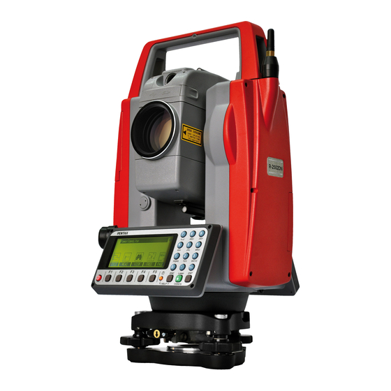
Pentax R-2500DN Series Instruction Manual
Total station
Hide thumbs
1
Table Of Contents
2
3
4
5
6
7
8
9
10
11
12
13
14
15
16
17
18
19
20
21
22
23
24
25
26
27
28
29
30
31
32
33
34
35
36
37
38
39
40
41
42
43
44
45
46
47
48
49
50
51
52
53
54
55
56
57
58
59
60
61
62
63
64
65
66
67
68
69
70
71
72
73
74
75
76
77
78
79
80
81
82
83
84
85
86
87
88
89
90
91
92
93
94
95
96
97
98
99
100
101
102
page
of
102
Go
/
102
Contents
Table of Contents
Bookmarks
Table of Contents
Table of Contents
Exemption Clause
Copyright
Precautions Regarding Safety
Warning
Usage Precautions
1 Basic Operation
Names of Parts
Standard Equipment
Unpacking and Packing
Removing and Attaching the Battery
How to Charge the Battery
Inserting and Removing of Various SD Cards
Inserting SD Card
Removing SD Card
Inserting SD Card for Camera Data
Removing SD Card for Camera Data
Suitability of SD Card
Inserting and Removing of Various USB Cables
Connecting USB Cable
Removing USB Cable
Inserting USB Cable for Camera Data
Removing USB Cable for Camera Data
About Recorded Data
About Measure Data
About Photography Data
2 Display and Keyboard
Operation Key
Function Key
Alphanumeric Input
Laser Pointer
3 Preparation for Surveying
Centring and Levelling of the Instrument
Laser Plummet
Levelling with Circular Vial
Levelling with the Plate Vial
Eyepiece Adjustment
Target Sighting
Attachment and Detachment of Tribrach
4 Turning the Power on
Turning the Power on and off
Adjusting LCD Contrast
Adjusting Illumination Brightness
Adjusting Reticle Illumination
5 Angle Measurement
Measuring an Angle
Resetting the Horizontal Angle to
Holding the Horizontal Angle
Inputting an Arbitrary Horizontal Angle
Displaying the % Slope of the Vertical Angle
Changing the Horizontal Angle from Clockwise to Counter Clockwise
6 Distance Measurement
Target Setting
Distance Measurement
Quick Mode
7 Correction Mode
Changing the Target Constant
Changing the Temperature
Changing the Atmospheric Pressure
Changing the Ppm Value
8 Initial Setting
Overview
Entering the Mode for Initial Setting
Entering the Mode for Initial Setting
Entering the Mode for Setting of Data and Time
Example of Changing an Initial Setting Content (Selection of Atmospheric Correction)
Initial Setting
Initial Setting
Setting of Date and Time
9 Accessing the Functions
Accessing by Help Key
Accessing by
10 Digital Camera
Turning the Camera on and off
Taking Pictures
Taking Pictures and Measuring Distance at the same Time
Taking Pictures Without Measuring Distance
Zooming
Slide Show
Playing Back Images
Rotating Images
Searching Images
Deleting Images
Adding Pointcode to Images
Displaying Measured Data
Zooming Images
Moving Images
Setup
Adjusting the Camera Settings
Adjusting Point Mark Position
Correct Center Mode
11 Data Collector
12 Checks and Adjustments
Plate Level
Circular Vial
Vertical Reticle
Perpendicularity of Line of Sight to Horizontal Axis
Vertical 0 Point Error
Offset Constant
Beam Axis and Line of Sight
The EDM Beam Axis
13 Appendix
Warning and Error Messages
Atmospheric Correction
Hpa and Mmhg Conversion Table
Error When no Atmospheric Correction Is Made
Atmospheric Refraction and Earth Curvature Correction
Distance Range
Specifications
14 Notice to the User of this Product
Specifications of Laser Radiation
The Following Labels Are Affixed to and Must Remain Attached to this Laser Product
Caution to Maintain the Safety in Compliance with the Standard
Labelling
15 Fcc Related
FCC Statement
FCC Radiation Exposure Statement
Advertisement
Quick Links
1
Angle Measurement
Download this manual
R-2500DN
INSTRUCTION MANUAL
TOTAL STATION
R-2501DN,R-2502DN
R-2503DN,R-2505DN
Basic Procedures
SERIES
TI Asahi Co.,Ltd.
International Sales Department
4-3-4 Ueno Iwatsuki-Ku,Saitama-Si
Saitama,339-0073 Japan
Tel, +81-48-793-0118
Fax, +81-48-793-0128
E-mail : international@tiasahi.com
PENTAX
Ⓡ
Table of
Contents
Previous
Page
Next
Page
1
2
3
4
5
Advertisement
Table of Contents
Need help?
Do you have a question about the R-2500DN Series and is the answer not in the manual?
Ask a question
Questions and answers
Related Manuals for Pentax R-2500DN Series
Measuring Instruments Pentax R-315EX(NX) Instruction Manual
R-300x series basic (80 pages)
Measuring Instruments Pentax R-315(N) Instruction Manual
R-300 series electronic total station (91 pages)
Measuring Instruments Pentax R-422VN Instruction Manual
R-400v series (71 pages)
Measuring Instruments Pentax R-422VN Instruction Manual
For r-400v series (142 pages)
Measuring Instruments Pentax R-2503DN Instruction Manual
Total station (102 pages)
Measuring Instruments Pentax Visio R-400VDN Series Quick Reference Manual
(56 pages)
Measuring Instruments Pentax R-2500NS Series Instruction Manual
(145 pages)
Measuring Instruments Pentax R-2501NS Instruction Manual
(72 pages)
Measuring Instruments Pentax R-200 Series Instruction Manual
(169 pages)
Measuring Instruments Pentax R-205N Instruction Manual
(169 pages)
Measuring Instruments Pentax TH-E10 Instruction Manual
Electronic theodolite (63 pages)
Measuring Instruments Pentax ETH-302 Instruction Manual
2/5/10/20 sec. angle accuracy detachable tribrach (48 pages)
Measuring Instruments Pentax PTS-V2 Instruction Manual
Electornic total station (93 pages)
Measuring Instruments Pentax PTS-II05 Instruction Manual
Electronic total station (47 pages)
Measuring Instruments Pentax Honeywell 1/21 Degree Spotmeter Operating Manual
(8 pages)
Measuring Instruments Pentax FX-1DC Instruction Manual
Theadolite (55 pages)
This manual is also suitable for:
R-2501dn
R-2502dn
R-2503dn
R-2505dn
Table of Contents
Print
Rename the bookmark
Delete bookmark?
Delete from my manuals?
Login
Sign In
OR
Sign in with Facebook
Sign in with Google
Upload manual
Upload from disk
Upload from URL


Need help?
Do you have a question about the R-2500DN Series and is the answer not in the manual?
Questions and answers