Table of Contents
Advertisement
ToTal STaTion
r-400V
InstructIon
manual
BaSic ProcedureS
for r-400V serIes
r-422Vn
r-423Vn
r-425Vn
r-435Vn
TI Asahi Co., Ltd.
International sales Department
3f aum Bldg. 3-37-14,
Hazawa, nerima-Ku
tokyo, Japan 176-0003
tel: +81-3-5912-7072
fax: +81-3-5912-7074
e-mail: international@tiasahi.com
serIes
Advertisement
Table of Contents

Related Manuals for Pentax R-422VN


Summary of Contents for Pentax R-422VN
- Page 1 ToTal STaTion r-400V serIes InstructIon manual BaSic ProcedureS for r-400V serIes r-422Vn r-423Vn r-425Vn r-435Vn TI Asahi Co., Ltd. International sales Department 3f aum Bldg. 3-37-14, Hazawa, nerima-Ku tokyo, Japan 176-0003 tel: +81-3-5912-7072 fax: +81-3-5912-7074 e-mail: international@tiasahi.com...
-
Page 2: Table Of Contents
CONTENTS GENERAL Contents Exemption clause Copyright Precautions regarding safety Warning Usage Precautions 1. BASIC OPERATION 1.1 Names of parts 1.2 Standard equipment 1.3 Unpacking and packing 1.4 Removing and attaching the Battery 1.5 How to charge the Battery 1.6 External connections 2. - Page 3 6. DISTANCE MEASUREMENT 6.1 Target setting 6.2 Distance measurement 6.3 Quick mode 7. CORRECTION MODE 7.1 Changing the target constant 7.2 Changing the temperature 7.3 Changing the atmospheric pressure 7.4 Changing the ppm value 8. INITIAL SETTING 8.1 Overview 8.2 Entering the mode for initial setting 1 8.3 Entering the mode for initial setting 2 8.4 Entering the mode for initial setting 3 8.5 Entering the mode for initial setting 4...
- Page 4 12.4 Error when no atmospheric correction is made 12.5 Atmospheric refraction and earth curvature correction 12.6 Distance range 12.7 Specifications 13. Notice to the user of this product 13.1 Specifications of Laser Radiation 13.2 The following labels are affixed to and must remain attached to this laser product.
-
Page 5: Exemption Clause
Before using this product, be sure that you have thoroughly read and understood this instruction manual to ensure proper operation. After reading this manual, be sure to keep in a convenient place for easy reference. Exemption clause 1) TI Asahi Co.,Ltd. (TIA) shall not be liable for damage caused by Acts of God, fire, alteration or servicing by unauthorized parties, accident, negligence, misuse, abnormal operating conditions. -
Page 6: Precautions Regarding Safety
PRECAUTIONS REGARDING SAFETYxxxx xxxx xxxxx Safety precautions (Must be followed) The following items are intended to prevent possible injury to the user or other people and/or damage to the instrument before it occurs. These safety precautions are important to the safe operation of this product and should be observed at all times. - Page 7 Do not aim the laser beam at a person as it is harmful to the eyes and body. Receive the examination treatment by the doctor when the eyesight or body trouble is doubted by any chance. • Electro-Magnetic Compatibility (EMC): This instrument complies with the protection requirement for residential and commercial areas.
- Page 8 • Do not short the poles of the battery or charger as there is a risk of injury or fire. • Do not touch any fluid which may leak from the battery as there is a risk of chemical burn injury or reaction.
-
Page 9: Usage Precautions
Usage precautions xxxx xxxxxxxxx Surveying instruments are high-precision instruments. In order to assure that the Electronic Total Station R-400V series product which you have purchased will provide long-lasting maximum performance, the precautions in this manual must be followed. Make sure to follow these instructions and use this product properly at all times. - Page 10 [Battery & charger] • Do not use any battery or battery charger that is not approved by Pentax as it entails a risk of damaging the instrument. • If water should happen to splash on the instrument or the battery, wipe it off immediately and allow it to dry in a dry location.
- Page 11 [Checks and repairs] • Always check the instrument before beginning work and check that the instrument is maintaining the proper level of precision. Pentax bears absolutely no responsibility for damages due to survey results obtained from surveys conducted without an initial instrument check.
-
Page 12: Basic Operation
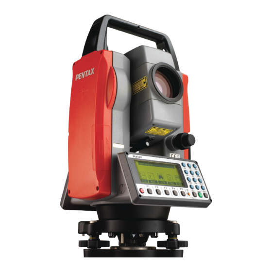
1. BASIC OPERATION 1.1 Names of parts Detachable type Top handle Collimator Focus ring Eyepiece ring Eyepiece Instrument height mark Laser indicator Battery latch Plate vial Battery pack SD & USB cover Telescope tangent screw Display panel Telescope clamp screw Key board Clamp screw Detaching knob... -
Page 13: Standard Equipment
1.2 Standard equipment • Instrument • Carrying case • BP02 battery • BP03/AC01 charger • Power supply cord • Plumb bob • Plummet hook • Hexagonal wrench • Adjusting pin • Screwdriver • Rain cover • Quick Reference Guide • CD-ROM (Basic operation & Special Functions manual) •... -
Page 14: How To Charge The Battery
① Rotate the knob above the battery pack counter clockwise. ② Lift up the battery pack and remove it from the instrument. [Attaching the Battery] ① Place the channel on the bottom of the battery pack. ② Onto the protrusion of the instrument and push the battery pack down into place. ③... -
Page 15: Display Panel
③ Insert the power supply plug of the power supply code in the outlet of AC power supply. [Installation of battery] ① Draw the battery to the lock lever side and put it on the battery pocket. The battery is firmly installed on the battery pocket. -
Page 16: External Connections
⑤ Discharge button : Discharge lamp lights when you push this button, and the discharge of battery begins. [How to charge] ① It begins charging automatically when you set the battery packing in the charger which beams the power supply lamp. ②... - Page 17 SD cards can be used with the R-400V series. This test has been done with only the Pentax R-400V series Total Station, but no other Pentax Total Stations. When using with other Pentax Total Stations, please contact us to confirm if it works properly.
- Page 18 ② When writing / reading text, it is necessary to be able to read/write text file. [Connecting USB cable] ① Open the SD & USB cover. ② Insert the USB connector into the USB port in the right direction. ③ After the USB cable is removed, close the SD & USB cover completely.
-
Page 19: Display And Keyboard
2. DISPLAY AND KEYBOARD 2.1 Display and keyboard Alphanumeric and +/- key Enter key Laser key Power supply key Function key Illumination key ESC key 2.2 Operation keys Description [POWER] ON/OFF of power supply. [ESC] Returns to previous screen or cancels an operation. [ILLU] Turns the illumination of the LCD display and telescope reticle on and off. -
Page 20: Function Keys
2.3 Function keys Display F. Key Description MODE A [MEAS] Pressing this key one time measures the distance in normal mode. Another measurement type can be selected by InitialSetting 2. Pressing this key twice measures the distance in coarse mode. Another measurement type can be selected by initial setting 2. - Page 21 [Other functions] Moves the cursor to the left. ▽ Moves the cursor to the right. ▽ Moves the cursor up. ▽ Moves the cursor down. ▽ Goes back five items on the screen. [ △ ] Gose forward five items on the screen. [ ▽...
-
Page 22: Alphanumeric Input
2.4 Alphanumeric input The point name is input by the alphanumeric keys as following. Letter under key Letter & figure order to input [@][.][_][-][:][/][0] PQRS [P][Q][R][S][p][q][r][s][1] [T][U][V][t][u][v][2] WXYZ [W][X][Y][Z][w][x][y][z][3] [G][H][I][g][h][i][4] [J][K][L][j][k][l][5] [M][N][O][m][n][o][6] [ ][?][!][_][ ][^][|][&][7] [A][B][C][a][b][c][8] [D][E][F][d][e][f][9] [.][,][:][;][#][(][)] [+/-] [+][-][*][/][%][=][<][>] 2.5 LD POINT, Laser pointer The Laser pointer function turns the laser beam on continuously to become the aiming point so that visual confirmation is possible. -
Page 23: Preparation For Surveying
3. PREPARATION FOR SURVEYING 3.1 Centring and Levelling of the Instrument [Setting up the instrument and the tripod] ① Adjust the tripod legs so that a height suitable for observation is obtained when the instrument is set on the tripod. ②... - Page 24 [Brightness adjustment of laser] Sometimes the state of the surface of the ground mark or a surrounding environmental does not allow observing the laser spot easily. Please adjust the brightness of the laser if necessary. If [Laser] + [F4] [PLUM.ADJ] are pressed in due course., the brightness adjustment screen of the laser plummet device, is displayed.
-
Page 25: Levelling With Circular Vial
3.3 Levelling with circular vial Tripod is adjusted according to the following points by extending or contracting the legs so that the bubble of the Circular vial goes to the centre of the circle. • Shorten the leg at the side of the bubble or extend the leg opposite of the bubble to position the bubble in the centre of the vial circle. -
Page 26: Eyepiece Adjustment
3.5 Eyepiece adjustment [Eyepiece adjustment] The eyepiece adjustment is performed before target sighting. Vertical line (single) ① Remove the telescope lens cap. Horizontal line ② Point the telescope at a bright object, and rotate the eyepiece ring full counter clockwise. ③... -
Page 27: Target Sighting
3.6 Target sighting [Target sighting by Manual focus] ① Loosen the telescope clamp and horizontal clamp screws. ② Point the telescope at the target using a collimator. ③ Tighten the above two screws. ④ Adjust the eyepiece. ⑤ Look through the telescope and then rotate the Focus ring and stop it where the target can be clearly seen and the target image does not move in relation to reticle even if your eye is vertically and horizontally moved. -
Page 28: Attachment And Detachment Of Tribrach
3.7 Attachment and detachment of tribrach The tribrach of R-422VN,R-423VN, and R-425VN can be detached from the instrument, if required when replacing the instrument with a prism for example. [Detachment] First loosen the recessed screw with a screwdriver, then rotate the locking knob until the arrow points upward, and lift the instrument up. -
Page 29: Turning The Power On
4. TURNING THE POWER ON 4.1 Turning the power on and off To set power on: To shut down: To turn the power supply off, press the I/O key for more than 1 second and then release it. Power turns OFF. NOTE: The power is automatically turned off after 10 minutes of inactivity (Factory default setting). -
Page 30: Adjusting Illumination Brightness
4.3 Adjusting illumination brightness Press [F5] while holding down the Illumination key to access the screen for adjusting illumination brightness. Pressing the [F1] [ ] will decrease brightness, while pressing the [F2] [ ] will increase brightness. Press [ENT] to exit adjustment mode and return to the previous screen. -
Page 31: Angle Measurement
5. ANGLE MEASUREMENT 5.1 Measuring an angle Aim at the first target, then press [F3] [0 SET] twice in succession to reset the horizontal angle to 0. Aim at the second target, then read the horizontal angle. Pressing [F4] [DISP] displays the vertical angle. •... -
Page 32: Holding The Horizontal Angle
5.3 Holding the horizontal angle To hold the horizontal angle currently being displayed, press [F3] [HOLD] twice in succession. The horizontal angle value is displayed in reverse video when being held. • lf you want to hold the horizontal angle when you are in MODE A, press [F5] [MODE] first to switch to MODE B, then press [F3] [HOLD]. -
Page 33: Displaying The Slope % Of The Vertical Angle
Press the numeric key as 123.4520. Press the [ENT] key to accept the horizontal angle set to 123° 45' 20" and change the screen to MODE • The former data is called by pressing the [CLEAR] key again. 5.5 Displaying the slope % of the vertical angle Press [F5] [MODE] to enter MODE B. -
Page 34: Changing The Horizontal Angle From Clockwise To Counter Clockwise
• To return the screen from the slope (%) display to the 360° scale, also take above same steps by entering MODE B. • If the slope (%) exceeds [+/-] 1000%, “Out of grade range” is displayed, indicating that the current vertical angle cannot be measured. -
Page 35: Distance Measurement
6. DISTANCE MEASUREMENT 6.1 Target setting The target mode and its Constant of current setting are shown at the left of the battery mark. For example in case of each Constant 0, Reflectorless (Non-Prism); N 0, Prism; P 0 Pressing [F2] [TARGET] changes the target mode. •... -
Page 36: Distance Measurement
right angle, there is a possibility that correct distance measurement may be impossible by dispersion or reduction of laser beam. [Applied measurement range by each target mode] • When a wrong target mode is selected, a correct distance cannot be measured. Please select a correct target mode and measure. -
Page 37: Quick Mode
• If the shot count for distance measurement has been set to 2 or more in “initial setting 2”, the distance is measured for the specified number of times to display the averaged value. Example: “TRACK CONT” at second MEAS (Factory default setting) Collimate the telescope at a Target and press [F1] [MEAS] twice to start measuring the distance. -
Page 38: Correction Mode
7. CORRECTION MODE 7.1 Changing the target constant Changing the Target Constant can be performed only when the Reflector sheet and Prism Constant setting are “INPUT” in initial setting 1. Example: Prism Constant -25mm setting Press [F4] [CORR] in MODE B. (If the instrument is in MODE A, press [F5] [MODE] to enter MODE B.) Press the [F5] [SELECT] to enable... -
Page 39: Changing The Temperature
• The factory initial of Reflector sheet Constant and Prism Constant are 0. • Once set, each Constant remains in memory even after the power is turned off. 7.2 Changing the temperature The temperature setting can be changed only when “ATM CORR” has been set to “ATM INPUT”... -
Page 40: Changing The Atmospheric Pressure
• Temperature correction is based on 15°C. If this instrument is used without correcting the temperature, a distance error per 100m is about -0.1mm per +1°C as a temperature difference from 15°C. A distance error per 100m is about 0.1mm per -1°C as a temperature difference from 15°C. (For more accurate values, See “12.4 Error when no atmospheric correction is made”.) 7.3 Changing the atmospheric pressure The atmospheric pressure setting can be changed only when “ATM CORR”... -
Page 41: Changing The Ppm Value
• Once set, the pressure is displayed at the centre of the top of the measurement screen. • The factory initial of pressure is “1013hPa”. • Once set, the pressure remains in memory even after the power is turned off. •... -
Page 42: Initial Setting
8. INITIAL SETTING 8.1 Overview For the R-400V series, you can select and save the desired setting for a variety of prescribed instrument conditions, called initial setting. The Initial Setting is saved in five modes, “initial setting 1”, “initial setting 2”, “initial setting 3”, “initial setting 4”, and “initial setting 5”... -
Page 43: Entering The Mode For Initial Setting
8.5 Entering the mode for initial setting 4 Press the [POWER] key while holding [F4] key down to access the screen for initial setting 4. • Select the item of interest in the same way as in the mode for initial setting 4. 8.6 Entering the mode for initial setting 5 Press the [POWER] key while holding [F5] key down to access the screen for initial setting 5. -
Page 44: Example Of Changing An Initial Setting Content (Selection Of Atmospheric Correction)
8.7 Example of changing an initial setting content (selection of atmospheric correction) This section describes the operating procedures for selecting “1.ATM CORR” in initial setting 1 as an example of changing an initial setting content. Use this example as a reference when changing other items because it is also applicable to the operating procedures for changing them. -
Page 45: Initial Setting
5. Selection of Tilt Compensation: [COMP AXIS] Select whether Tilt Compensation is to be single-axis compensation, dual-axis compensation or disabled (NIL). X1.3 R-422VN is selectable up to 3 AXIS. AXISXXXXXXX R-423VN, R-425VN, R-435VN are selectable up to 2 2.2 AXIS AXIS. -
Page 46: Initial Setting 2
8.9 Initial setting 2 1. Selection of the Minimum Distance measurement unit X1.1mm/OFFXX and Quick Mode : [EDM MIN DISP/QUICK] XXXX More fine angle view is necessary, select 0.1mm, 2.1mm/ON Besides that, select 1mm/OFF. 3.0.1mm When using Quick Mode, select 1mm/ON. X1.1 2. - Page 47 X1.Z.0 XXXXX 9. Selection of Vertical angle style: [V.ANG. STYLE] Select whether the 0 point for vertical angle is set to be 2.H.0 “Z.0”, “H.0” or “COMPAS”. 3.COMPAS 10. Selection of Automatic power-off function X1.10 MIN : [AUTO OFF] 2.20 MIN Select the time interval (10, 20 or 30 minutes) for activating the automatic power-off function, or select NIL, 3.30 MIN...
-
Page 48: Initial Setting
started to when measured data is displayed. 16. Selection of Priority Display: [PRIORITY DISP.] 1.HA Select the display order of the sets of display items which 2.HA pressing the [DISP] key cycles through. The set of display 3.HA VA HD SD items selected here appears first after the power is turned 8.10 Initial setting 3 1. -
Page 49: Initial Setting
8.11 Initial setting 4 1. Selection of Temperature unit setting: [TEMP. UNIT] X1.゚ Select °C or °F as the unit for Temperature. CXXXXXXXXXX 2.゚F 2. Selection of Pressure unit setting: [PRESS UNIT] X1. hPa XXXXX Select hPa (hectopascal), mmHg, inchHg as the unit for 2. - Page 50 5. Selection of Control signal: [SIGNAL CONTROL] X1.ON Select whether the control signal is effective or not. XaXXXXXX 2.OFF X1.ON 6. Selection of XON/XOFF: [XON/XOFF] XaXXXXXX Select whether to enable or disable XON/XOFF. 2.OFF X1.NILXXXXXXXX 7. Selection of Through command : [THROUGH COMMAND] Select whether to disable data output without receiving any data request command...
-
Page 51: Accessing The Functions
9. ACCESSING THE FUNCTIONS 9.1 Accessing by help key You can use the [HELP] key to display specific initial setting (such as the prism constant and priority mode). Press the [ILLU]+[ESC] key in MODE A or B. The help menu will then be displayed. Press [F1] [ △ ][F2] [ ▽ ] or [F3] [ ] [F4] [ ] to position the cursor to the desired item. -
Page 52: Instrument Setting Items
TRACK SHOT, MEAS. CONT, MEAS. SHOT PRIORITY DISP. HA/HD/VD HA/VA/SD, HA/VA/HD/SD/VD COMP AXIS 3 AXIS 2 AXIS, 1AXIS, NIL (R-422VN) 2 AXIS 1 AXIS, NIL (R-423VN, R- 425VN, R-435VN) LD. PLUM. LONG RANGE MES. (when target is Ref.less) ATM UNIT TEMP. -
Page 53: Data Collector
10. DATA COLLECTOR The instrument can communicate directly with a computer through the RS-232c interface. By use of a data collector you can automate data entry, from the collection of survey data to the transfer of the data to a computer. This is useful in saving time and protecting data integrity. For instructions about the connection with a data collector and the handling, please refer to the “Instruction manual”... -
Page 54: Circular Vial
Leveling screw to be adjusted. Plate vial Leveling screw to be adjusted. [Adjustments] ① If the bubble of the plate lever moves from the center, bring it half way back to the center by adjusting the leveling screw(s) which is parallel to the plate level. ②... -
Page 55: Vertical Reticle
• Tighten the screws equally after the above adjustment. Circular vial Circular vial adj. screw 11.3 Vertical reticle [Checks] ① Set the instrument up the tripod and carefully level it. ② Sight the target Point A with telescope. ③ Using the telescope fine adjustment screws, move Point A to the edge of the field of view by screw (Point A’). -
Page 56: Perpendicularity Of Line Of Sight To Horizontal Axis
11.4 Perpendicularity of line of sight to horizontal axis [Checks] ① Position a target Point A at a distance 30m - 50m away from the instrument, and sight it with the telescope. ② Loosen the telescope lock screw and turn the telescope until a point is sighted at a distance roughly equal to that of Point A. -
Page 57: Vertical 0 Point Error
When a centre part where a cross intersection and the laser mark look the brightest shifts by 0.5mm or more (at the instrument height 1.5m), it is necessary to adjust it. A repair engineer does this adjustment. Please contact the PENTAX dealer. 11.7 Offset constant The offset constant rarely changes. -
Page 58: Beam Axis And Line Of Sight
[Checks] ① Locate points A, B and C at about 50m intervals on even ground. ② Set up the instrument at point A, and measure the distances between AB and AC. ③ Set up the instrument at point B, and measure the distance BC. ④... -
Page 59: The Edm Beam Axis
• This check should be done under good weather conditions. 11.9 The EDM beam axis The distance measurement (EDM) beam axis is adjusted to be aligned to the sighting axis of the telescope, but it can be changed a little in case of rapid temperature change, shock or aging. -
Page 60: Appendix
At the procedure 4. above, if the “Centre” of laser spot is not within the internal circle (10mm) of the target plate, the adjustment is necessary. Please contact your PENTAX dealer. 12. APPENDIX 12.1 Warning and Error Messages Warning Meaning... -
Page 61: Atmospheric Correction
Error Message Meaning What to do Turn the power off, EDM ERROR Distance measurement and then turn on 04 -05, 34-39, 50-53 system problem again. ETH ERROR 70-76 Angle measurement system problem Repair is needed MEMORY ERROR 19 Memory problem when the message ERROR PS DATA of appears consistently. -
Page 62: Error When No Atmospheric Correction Is Made
1200 [Converting from mmHg to hPa] Unit:hPa mmHg 1000 1013 1027 1040 1053 1067 1080 1093 1107 1120 1133 1147 1160 1173 1187 1200 1213 1227 1240 1253 1267 1280 1293 1307 1320 12.4 Error when no atmospheric correction is made When measurement is carried out with no atmospheric correction (with the settings fixed at a temperature of 15°C and an atmospheric pressure of 1013hPa or 760mmHg), the error per 100 meters in temperature and pressure will be shown in the tables below. -
Page 63: Atmospheric Refraction And Earth Curvature Correction
-3.3 -7.4 -11.5 12.5 Atmospheric refraction and earth curvature correction • Atmospheric refraction and earth curvature correction refers to correcting both the bending of the light beam caused by atmospheric refraction and the effect on the height differential and horizontal distance caused by the earth curvature. •... -
Page 64: Distance Range
12.6 Distance range Generally speaking, the maximum range which can be measured varies considerably depending on the atmospheric conditions. For this reason, the specifications illustrate the values for both good and normal weather conditions. It is extremely difficult to judge when weather conditions are “Good” and when they are “Normal”. -
Page 65: Specifications
12.7 Specifications R-422VN R-423VN R-425VN R-435VN Telescope Magnification Effective aperture 45mm(EDM45mm) Resolving power Field of view 1 30 (2.6%) Minimum focus 1.0m Focus Manual Distance measurement Visible Laser : Class Ⅲa (3R)(Reflectorless)/ Laser class Class Ⅱ(2)(Prism,sheet) Measurement range(Good conditions) ※3 Reflectorless ※1... - Page 66 Plate vial 30"/1div. Circular level 8'/2mm Plummet Visible laser: 0.5mm (Instrument height:1.5m) Base Detachable Shifting Dust and Water Protection IP56(Instrument only) Ambient temperature -20℃∼+50℃/-4 F∼122 F (Working range) Tripod thread 5/8"x11 M35 P2 Dimensions/Weight Dimensions 180(W) 342(H) 177(L)mm Weight(incl. Battery) 5.7kg 5.5kg Carrying case...
- Page 67 Kodak Gray Card. (KODAK is a trademark of Eastman Kodak Company) Reflector sheet: PENTAX genuine Reflector sheet The measurement range may vary by conditions of the environment. Normal conditions: 20km visibility with slight shimmer Good conditions: 40km visibility, overcast, no heat, no shimmer and moderate wind.
-
Page 68: Notice To The User Of This Product
13. NOTICE TO THE USER OF THIS PRODUCT To assure compliance with the Safety standard 21 CFR, Chapter 1., Subchapter J., the U.S. Bureau of Radiological Health requires the following information to be provided to user.: It can be dangerous to look into the beam with optical equipment such as binoculars and telescopes. -
Page 69: Caution To Maintain The Safety In Compliance With The Standard
C) Maintenance and repair not covered in this manual must be done by an authorized Pentax dealer. D) The Laser beam emission by the Distance measurement can be terminated by Pressing [ESC] key. -
Page 70: Labelling
13.4 Labelling Aperture label Identification Warning logotype Laser beam is transmitted from this aperture For North America Certification LED is turned on at the time of emission Warning logotype Warning logotype Aperture label Laser beam is transmitted from this aperture... - Page 71 TI Asahi Co., Ltd. International Sales Department 3F AUM Bldg. 3-37-14, Hazawa, Nerima-Ku Tokyo, Japan 176-0003 Tel: +81-3-5912-7072 Fax: +81-3-5912-7074 E-mail: international@tiasahi.com Japan Surveying Instruments Manufacturers’ Association Member symbol of the Japan Surveying Instruments Manufacturers’ Association representing the high quality surveying products.
Need help?
Do you have a question about the R-422VN and is the answer not in the manual?
Questions and answers