Table of Contents
Advertisement
Owner's Manual
Original Instructions
Commercial Air Conditioners
Multi Variable Air Conditioners
Cassette Type Indoor Unit
Models:
GMV-ND22T/C-T
GMV-ND28T/C-T
GMV-ND36T/C-T
GMV-ND45T/C-T
GMV-ND50T/C-T
GMV-ND56T/C-T
GMV-ND63T/C-T
GMV-ND71T/C-T
GMV-ND80T/C-T
GMV-ND90T/C-T
GMV-ND100T/C-T GMV-ND112T/C-T
GMV-ND125T/C-T GMV-ND140T/C-T
GMV-ND160T/C-T
Advertisement
Table of Contents

Related Manuals for Gree GMV-ND22T/C-T


Summary of Contents for Gree GMV-ND22T/C-T
- Page 1 Owner's Manual Original Instructions Commercial Air Conditioners Multi Variable Air Conditioners Cassette Type Indoor Unit Models: GMV-ND22T/C-T GMV-ND28T/C-T GMV-ND36T/C-T GMV-ND45T/C-T GMV-ND50T/C-T GMV-ND56T/C-T GMV-ND63T/C-T GMV-ND71T/C-T GMV-ND80T/C-T GMV-ND90T/C-T GMV-ND100T/C-T GMV-ND112T/C-T GMV-ND125T/C-T GMV-ND140T/C-T GMV-ND160T/C-T...
- Page 2 To Users Thank you for selecting Gree product. Please read this instruction manual carefully before installing and using the product, so as to master and correctly use the product. In order to guide you to correctly install and use our product and achieve expected operating effect, we hereby instruct as...
- Page 3 Exception Clauses Manufacturer will bear no responsibilities when personal injury or property loss is caused by the following reasons: (1) Damage the product due to improper use or misuse of the product; (2) Alter, change, maintain or use the product with other equipment without abiding by the instruction manual of manufacturer;...
-
Page 4: Table Of Contents
Contents 1 Safety Notices (Please be Sure to Abide) ..............1 2 Product Introduction ....................4 2.1 Names of Key Components ....................4 2.2 Rated Working Condition ..................... 4 3 Preparations for Installation ..................4 3.1 Standard Fittings ........................4 3.2 Installation Position Selection .................... -
Page 5: Safety Notices (Please Be Sure To Abide)
Multi Variable Air Conditioners Cassette Type Indoor Unit 1 Safety Notices (Please be Sure to Abide) WARNING: If not abide strictly, it may cause severe damage to the unit or the people. NOTE: If not abide strictly, it may cause slight or medium damage to the unit or the people. This sign indicates that the operation must be prohibited. - Page 6 Multi Variable Air Conditioners Cassette Type Indoor Unit Diameter of power cord must After the power cord is be large enough. Damaged connected, please install the power cord and connecting cover of electric box to avoid wire must be replaced by danger.
- Page 7 Gree Electric Appliances, Inc. of Zhuhai will not assume responsibility for any personal injury or property loss caused by improper installation, improper debugging, unnecessary repair or not following the instructions of this manual.
-
Page 8: Product Introduction
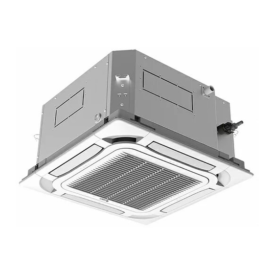
Multi Variable Air Conditioners Cassette Type Indoor Unit 2 Product Introduction 2.1 Names of Key Components Fig.2.1 2.2 Rated Working Condition Indoor Side Condition Outdoor Side Condition Dry Bulb Temp℃ Wet Bulb Temp℃ Dry Bulb Temp℃ Wet Bulb Temp℃ Rated Cooling Rated Heating 3 Preparations for Installation NOTE! This picture is for reference only, please refer to the actual product;... -
Page 9: Installation Position Selection
Multi Variable Air Conditioners Cassette Type Indoor Unit Name Appearance Q'ty Usage Insulation To insulate the gas/ liquid pipe Sponge To insulate the drain pipe. Fastener To fasten the sponge. 3.2 Installation Position Selection (1) The appliance shall not be installed in the laundry. (2) The location should be able to withstand the weight of unit. -
Page 10: Requirements Of Communication Wire Selection
Multi Variable Air Conditioners Cassette Type Indoor Unit 3.3 Requirements of Communication Wire Selection NOTE! If air conditioner used under strong electronic-magnetic interference circumstance, STP (shielded twisted pair) communication cable must be adopted. 3.3.1 Selection of communication wire between indoor unit and wired controller Fig.3.3.1 Total length of communication wire between... -
Page 11: Wiring Requirement
Dimension of power cord and capacity of air switch. Minimum Sectional Minimum Sectional Air Switch Capacity Model Power Cord Size Area of Ground Wire Area of Power Cord (mm²) (mm²) GMV-ND22T/C-T GMV-ND28T/C-T GMV-ND36T/C-T GMV-ND45T/C-T GMV-ND50T/C-T GMV-ND56T/C-T GMV-ND63T/C-T 220-240V-1ph-50Hz GMV-ND71T/C-T 208-230V-1ph-60Hz... -
Page 12: Installation Instructions
Multi Variable Air Conditioners Cassette Type Indoor Unit 4 Installation Instructions 4.1 Indoor Unit Installation 4.1.1 Ceiling Opening Dimension and Suspension Bolt Position. Fig.4.1.1 Unit: mm Model GMV-ND22~160T/C-T 4.1.2 Suspend the Indoor Unit (1) Drill bolt holes and install bolts. 1) Stick the reference cardboard on the installation position;... - Page 13 Multi Variable Air Conditioners Cassette Type Indoor Unit Fig.4.1.4 (2) Install the indoor unit temporarily. Assemble suspension bolt on the expansion bolt, attach the hanger bracket to the suspension bolt. Be sure to fix it securely by using a nut and washer from upper and lower sides of the hanger bracket.
-
Page 14: Refrigerant Pipe Connection
Multi Variable Air Conditioners Cassette Type Indoor Unit 4.2 Refrigerant Pipe Connection (1) Aim the flaring port of copper pipe at the center of screwed joint and then tighten the flaring nut with hand as shown in Fig.4.2. (2) Tighten the flaring nut with torque wrench. Fig.4.2 Torque for tightening nut Pipe diameter (mm) - Page 15 Multi Variable Air Conditioners Cassette Type Indoor Unit (8) When the drainage pipelines are used for several units, the position of pipeline should be about 100mm lower than the drainage port of each unit. In this case, thicker pipes should be applied.
- Page 16 Multi Variable Air Conditioners Cassette Type Indoor Unit Unit:mm Fig.4.3.3 Unit:mm Model GMV-ND22~160T/C-T (9) Drain pipes should have a downward slope of at least 1%~2%, in order to prevent pipes from sagging, install hanger bracket at intervals of 1000~1500mm. Unit:mm Fig.
-
Page 17: Panel Installation
Multi Variable Air Conditioners Cassette Type Indoor Unit 4.3.3 Test of Drainage System (1) Please test drainage system after electric work is finished. Inject approximately 1L purified water to drain pan from air vent, ensure that not to splash the water over the electrical components (e.g. - Page 18 Multi Variable Air Conditioners Cassette Type Indoor Unit Fig.4.4.2 (3) Connect the decoration panel terminals (Female) to body terminals (male) as shown in Fig.4.4.3. Fig.4.4.3 4.4.2 Panel Installation (1) Detach the panel’s Corner Cap, there is a mark “piping side” on one of the 4 corners, adjust the panel direction so as to keep the mark and fittings on the same corner.
-
Page 19: Wired Controller Installation
Multi Variable Air Conditioners Cassette Type Indoor Unit Fig.4.4.4 4.5 Wired Controller Installation Wired controller is optional accessory. If wired controller is needed, please contact your local dealer and install the wired controller according to the instruction manual. NOTE! Do perform the commissioning operation before first use, automatic addressing or other settings, please refer to the manual of ODU. -
Page 20: Connection Of Wire And Patch Board Terminal
Multi Variable Air Conditioners Cassette Type Indoor Unit 5.1 Connection of Wire and Patch Board Terminal (1) The connection of wire (as shown in Fig.5.1.1). 1) Strip about 25mm insulation of the wire end by stripping and cutting tool. 2) Remove the wiring screws on the terminal board. 3) Shape the tail of wire into ring by needle nose plier, and keep the gauge of ring in accordance with screw. -
Page 21: Connection Of Communication Wire Between Indoor Unit And Outdoor Unit (Or Indoor Unit)
Multi Variable Air Conditioners Cassette Type Indoor Unit Fig.5.2 (1) Detach the electric box lid. (2) Let the power cord pass through the wiring through-holes. (3) Connect wires according to Fig.5.2. (4) Fix the power cord with wiring clamp. 5.3 Connection of Communication Wire between Indoor Unit and Outdoor Unit (or Indoor Unit) (1) Detach the electric box lid. -
Page 22: Connection Of Communication Wire For Wired Controller
Multi Variable Air Conditioners Cassette Type Indoor Unit Fig.5.3.2 5.4 Connection of Communication Wire for Wired Controller (1) Detach the electric box lid. (2) Let the communication wire pass through the wiring through-holes. (3) Connect the communication wire to terminal H1 and H2 of indoor 4-bit wiring board. (4) Fix the communication wire with clamp. -
Page 23: Instructions On Connecting Wired Controller And Indoor Units Network
Multi Variable Air Conditioners Cassette Type Indoor Unit 5.5 Instructions on Connecting Wired Controller and Indoor Units Network (1) Communication wire of indoor unit and outdoor unit (or indoor unit) is connected to D1, D2. (2) Wired controller is connected to H1, H2. (3) One indoor unit can connect two wired controllers that must be set as master one and slave one. -
Page 24: Routine Maintenance
Multi Variable Air Conditioners Cassette Type Indoor Unit 6 Routine Maintenance WARNING: ① Do turn off the unit and cut off the main power supply when cleaning the air conditioner to avoid electric shock or injury. ② Stand at solid table when cleaning the unit. ③... -
Page 25: Table Of Error Codes For Indoor Unit
Multi Variable Air Conditioners Cassette Type Indoor Unit 7 Table of Error Codes for Indoor Unit Error Error Error Content Content Content Code Code Code Indoor Units Incompatibility Indoor Unit Error Jumper Cap Error Error Indoor Unit Network Address Indoor Fan Protection Low Air Quality Warning Error ODU-IDU Incompatibility... -
Page 26: Troubleshooting
Multi Variable Air Conditioners Cassette Type Indoor Unit 8 Troubleshooting The air conditioner is not expected to be serviced by users. Incorrect repair may cause electric shock or fire, so please contact an authorized service center for professional service. The following checks prior to contact may save your time and money.
Need help?
Do you have a question about the GMV-ND22T/C-T and is the answer not in the manual?
Questions and answers