
Related Manuals for Tennsmith LM1014


Summary of Contents for Tennsmith LM1014
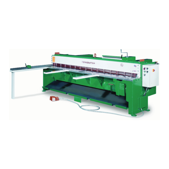
- Page 1 Model LM1014 Performance “F” MODEL LM1014 MECHANICAL SHEAR OPERATION, PARTS & MAINTENANCE MANUAL Model: Purchased From: Serial #: Date Received: 6926 Smithville Hwy., McMinnville, TN 37110 931-934-2211 / Fax: 931-934-2220 www.tennsmith.com...
- Page 2 TABLE OF CONTENTS SUBJECT PAGE NUMBERS SHEAR SPECIFICATIONS WARRANTY INFORMATION SAFETY LABELING AND INSTUCTIONS 4 - 9 INSTALLATION OPERATING INSTRUCTIONS 11 - 13 BLADE CLEARANCE/ADJUSTMENT BLADE ROTATION/REPLACING 15 - 16 BACKGAUGE INFORMATION HOLDDOWN INFORMATION SHEET SUPPORT SYSTEM INFORMATION MAINTENANCE 19 - 20 PARTS VIEW AND DESCRIPTIONS 21 - 34 ELECTRICAL DIAGRAM AND PARTS LIST...
-
Page 3: Year Limited Warranty
6,200 lbs. 3-YEAR LIMITED WARRANTY TENNSMITH machinery and component parts are carefully inspected at various stages of production and are tested and inspected prior to shipment. We agree that for a period of twelve (12) months from the date of delivery from our authorized distributor to replace, at our option, any machine (or component part thereof) proving defective within the above period. - Page 4 Please verify that the following safety decals are attached to the LM Shear. If you do not locate all of the decals, please contact Tennsmith to replace any missing or unreadable safety labels. NEVER operate this machine without the proper safety labeling.
-
Page 8: Safety Instructions
SAFETY INSTRUCTIONS Do not operate service or perform maintenance prior to reading and understanding the instruction manual. Become familiar with and understand the hazards and limitations of your shear. Wear approved eye protection and protective footwear while operating the machine. Be certain this machine is properly wired and grounded to conform to the National Electric Code. - Page 9 DANGER! Do not attempt to remove the hold down before inserting and bottoming out the hold down compression bolts (71). The compression bolts were shipped with the machine. When receiving the shear the bolts are located inside of the electrical box. Please remove them and store them in a location to be accessible.
-
Page 10: Electrical Specifications
The unit is shipped with a lifting bolt attached on the top of the cutter head. The shear should be lifted and positioned by using a sling or chain passed through the lifting bolt. CAUTION! The LM1014 shear weighs approximately 7,000 lbs. net. Be sure to verify the maximum load permissible for a given chain or sling. - Page 11 LM Control Box Overlay...
- Page 12 Please note if your switch does not illuminate in the out position, you must immediately replace the bulb located within the switch. It is unsafe to operate this shear without the illuminated switch. Please contact Tennsmith if you need assistance replacing the bulb. 2. To the right of the Push/Pull Switch is the Jog/Run Switch: This selector type switch is designated 2 on the previous page.
- Page 13 If you have any questions on this procedure, please consult the factory prior to any adjustments on your shear. 4. Stroke Selector Switch: This switch is located towards the bottom of the panel and is designated 5 on the previous page. The switch has two options: Cont –...
-
Page 14: Blade Clearance
BLADE CLEARANCE The blade clearance on the LM1014 was set at the factory to .003 in. on the ends of the blades with a .002 gap in the center of the machine. At this setting, your shear should provide satisfactory results over a broad range of materials and thickness. - Page 15 REPLACING/ROTATING BLADES The blades on the LM Series shears are four edged blades constructed of high carbon, high chromium tool steel. Top and bottom blades are interchangeable. Upon utilizing all four edges of you blades, you may return the blades to the factory for re-sharpening or to a qualified blade re-sharpener, such as a blade manufacturer.
- Page 16 With all bolts in place, securely torque the bolts while insuring that the blade is properly seated in the machined blade slot of the cutter head by using either a brass or wood pry bar. Repeat the above procedures similarly to reposition the bottom blade. Use the procedures outlined in the BLADE CLEARANCE section of this manual to reset the proper baled gap.
-
Page 17: Hold Down Adjustment
Hold Down Adjustment The following is the instructions to raise the hold down height to reduce the pressure (Hold down) on your LM shear: Using the jog mode, depress the jog button until the machine cutter head reaches the bottom or its lowest position. - Page 18 SHEET SUPPORT SYSTEM a. Single Stroke: When the foot pedal is activated, the sheet support will drop down and remain down until the cycle is complete and then return to the up position. b. Continuous Stroke: When the foot pedal is activated, the sheet support will drop down and stay down as long as the foot pedal is activated.
-
Page 19: Maintenance
MAINTENANCE On a monthly basis, remove the top cover (11) of each side panel and grease the gib plates (9, 10, 15). This can be best accomplished by jogging the cutter head down to the extreme down-stroke position, thus exposing a majority of the gib surface. WARNING! MAKE SURE THE POWER TO THE MACHINE HAS BEEN TURN OFF WHEN APPLING LUBRICATES. - Page 21 LM Machine PARTS View...
- Page 22 MODEL LM1014 PARTS LIST ITEM# LM PART# DESCRIPTION QTY. 1014001 CUTTER HEAD 101402L GIBB PLATE LEFT 101402R GIBB PLATE RIGHT 1014003 BLADE TOP & BOTTOM 1014004 SET SCREW, ROD MOUNTING 1014005 BOLT, BLADE MOUNTING 1014006 LOCK WASHER, BLADE 1014007 DOWEL PIN, GIBB PLATE...
- Page 23 MODEL LM1014 PARTS LIST Continued ITEM# LM PART# DESCRIPTION QTY. 1014041 ELECTRIC CONTROL BOX 1014042 SWITCH, FORWARD REVERSE 1014043 BOLT, TABLE MUNTING, TOP 1014044 BOLT, MATERIAL GUIDE BAR MOUNTING 1014045 MATERIAL GUIDE BAR 1014046 SCREW, SCALE MOUNTING, TABLE 1014047 SCALE, TOP...
- Page 24 LM 2x Back gauge Crank Assembly...
- Page 25 LM 2x Back gauge Crank Assembly Parts List ITEM# LM PART# DESCRIPTION QTY. 20083 THRUST WASHER 20085 LOCK WASHER, BOLT, SPROCKET MOUNTING 20086 SPACER RING, SPROCKET MOUNTING 20087 BEARING, SPROCKET MOUNTING 20088 SPROCKET 20089 CHAIN 20102 BOLT, SPROCKET AND SPACER BLOCK MOUNTING 20103 FLAT WASHER, BOLT, SPROCKET SPACER BLOCK 20139...
- Page 26 LM 2x Back gauge Pointer Assembly...
- Page 27 LM 2x Back gauge Pointer Assembly Parts List ITEM# LM PART# DESCRIPTION QTY. 20136 COVER, SCALE POINTER ASSEMBLY 137A 2137A SCALE, INCH/METRIC 30 ICHES 20138 SCREW, SCALE BRACKET AND COVER MOUNTING 3 20139 LOCK WASHER, SCREW, SCALE BRACKET 20140 BRACKET, SCALE MOUNTING 20141 BRACKET, ROD MOUNTING 20142...
- Page 28 LM 2x Back gauge Drive Assembly...
- Page 29 LM 2x Back gauge Arm Assembly...
- Page 30 LM 2x Back gauge Arm Assembly Parts List ITEM# LM PART# DESCRIPTION QTY. 20094 SET SCREW, SHAFT MOUNTING 20095 SUPPORT BLOCK, FRONT 20096 SET SCREW, SUPPORT BLOCK MOUNTING 20097 SUPPORT ROD 20098 SUPPORT BLOCK, REAR 20099 BOLT, REAR SUPPORT BLOCK ADJUSTING 20100 JAM NUT, BOLT, REAR SUPPORT BLOCK ADJ 20101...
- Page 31 LM Four Foot Squaring Arm...
- Page 32 LM Four Foot Squaring Arm Parts List ITEM# LM PART# DESCRIPTION QTY. 40005 BOLT, TABLE, SQUARING ARM MOUNTING 40006 LOCK WASHER, BOLT, TABLE SQ ARM MOUNTING 2 40046 SET SCREW, SCALE 40181 NUT, LOCK HANDLE, BLOCK SQ ARM 40185 RATCHET STUD, LOCK HANDLE, BLOCK SQ ARM 40186 HANDLE, LOCK HANDLE, BLOCK SQ ARM 40187...
- Page 33 LM Front Return Sheet Support System LM Front Return Sheet Support System ITEM# LM PART# DESCRIPTION QTY. FS10195 SUPPORT BRACKET, FRONT RETURN, SYSTEM 195A FS10195A SUPPORT BRACKET, FRONT RETURN, SYSTEM FS10197 LOCK WASHER, BRACKET MOUNTING FS10198 SCREW, BRACKET MOUNTING FS10199 WASHER, RACK MOUNTING FS10200 TEFLON WASHER, RACK MOUNTING...
- Page 34 LM Rear Sheet Support System LM Rear Sheet Support System Parts List ITEM# LM PART# DESCRIPTION QTY. RS5197 SCREW, BRACKET MOUNTING RS5198 LOCK WASHER, BRACKET MOUNTING RS5199 WASHER, RACK MOUNTING RS5200 TEFLON WASHER, RACK MOUNTING RS5201 STRIPPER BOLT, RACK MOUNTING RS5202 BRACKET, AIR CYLINDER MOUNTING RS5203...
- Page 35 LM1014 3 Phase - Front Sheet Support High Voltage Mains, AC Circuit Cutter Head Main Forward Disconnect Overload Reverse 5.0HP 208 V 3 PH 17.5 AMP 230 V 3 PH 15.2 AMP 460 V 3 PH 7.6 AMP Transformer 0.75 kva...
- Page 36 Motors and Brakemotors OPERATING INSTRUCTIONS 09 793 67 US Type BM (G) Brakes ≥ 230000 ohms = value of at least 1000 x V (e.g. at V = 230VAC: R insul 0.23M ohms). If the measured value is smaller, the motor should be dried Every SEW-Eurodrive motor is thoroughly tested, checked, and properly before use (for example, with hot air up to a maximum of 90°C or by re- packed prior to shipment.
- Page 37 Brake Coil Resistance Motor Frame DT71-80 DT80 DT90-100 DT100 DV112-132S DV132M-160M DV160L-225 Brake Size BM(G)05 BM(G)1 BM(G)2 BM(G)4 BM(G)8 BM15 BM30/31/32/62 Brake Torque (lb-ft) 0.89 - 3.7 4.4 - 7.4 3.7 - 14.8 17.7 - 29.5 7.00 - 55.3 18.4 - 110.6 36.9 - 442.5 (Ω) BRAKE VOLTAGE...
- Page 38 There are specific instances when the brake voltage can be tapped from the motor's terminal block. The advantage of brake systems wired in this way is when power is applied to the motor, the brake releases, (requiring no additional brake supply power wiring). The brake can be wired to the motor terminal block under the following conditions: a single speed motor;...
- Page 39 At the motor, measure the line voltage, line current and motor resis- A properly adjusted brake air gap is critical for correct operation. The fol- tance of all three phases. lowing table indicates the required air gap measurement. If all three phases read a similar current value the following condi- tions may exist: Motor Size Brake Size...
- Page 40 BM(G) Brake Cross Section and Exploded Views (1) Brake end shield (16) Dowel pin (2) Rubber sealing collar (17) Fan (3) Braking springs (18) N/A (4) Hand release lever (19) Brake adjustment nut (5) Releasing screw (20) Retaining stud (6) Closing plate (21) Brake coil body (7) Release arm (22) Stationary disc...
-
Page 41: Troubleshooting Chart
Troubleshooting Chart PROBLEM CAUSE REMEDY Motor not connected for proper supply Check connection diagram on conduit box voltage cover and correct the wiring. Supply voltage varies outside the allow- able tolerance causing an undervoltage or Assure correct supply voltage. overvoltage condition. Insufficient cooling air volume due to: Increase air flow: a. - Page 42 OPERATING INSTRUCTIONS Gearmotors and Gear Reducers 01 805 52 US GENERAL SHAFT MOUNTED REDUCERS These operationg instructions are intended to help you install and SEW-Eurodrive supplies the recommended hollowshaft mount- operate the drive. For trouble free service, proper installation and ing paste with every hollowshaft reducer.
- Page 43 LUBRICANTS LUBRICATION SCHEDULE FOR SEW-EURODRIVE GEAR UNITS Gear Ambient air Reducer Lubrication temperature Viscosity Mobil CHEVRON Shell Texaco Kluber Type Type range °F Grade Oil Co. Oil Co. Oil Co. Oil Co. Oil Co. Oil Co. Chevron Non-Leaded Mobilgear Shell Omala BP Energol Kluberoil VG220...
- Page 44 LUBRICANTS The approximate lubricant in US gallons and liters per mounting position is as follows: Mounting Position Gear Unit Gallons Liters Gallons Liters Gallons Liters Gallons Liters Gallons Liters Gallons Liters RX57 0.16 0.21 0.34 0.34 0.24 0.24 RX67 0.21 0.21 0.45 0.50...
- Page 45 LUBRICANTS The approximate lubricant in US gallons and liters per mounting position is as follows: Mounting Position Gear Unit Gallons Liters Gallons Liters Gallons Liters Gallons Liters Gallons Liters Gallons Liters 0.16 0.21 0.18 0.18 0.16 0.16 0.26 0.32 0.18 0.32 0.26 0.29...
- Page 46 LUBRICANTS The approximate lubricant in US gallons and liters per mounting position is as follows: Mounting Position Gear Unit Gallons Liters Gallons Liters Gallons Liters Gallons Liters Gallons Liters Gallons Liters 0.13 0.26 0.26 0.34 0.26 0.26 0.21 0.34 0.40 0.53 0.42 0.42...
- Page 47 LUBRICANTS The approximate lubricant in US gallons and liters per mounting position is as follows: Mounting Position Gear Unit Gallons Liters Gallons Liters Gallons Liters Gallons Liters Gallons Liters Gallons Liters 0.07 0.25 0.11 0.13 0.16 0.11 0.11 0.18 0.09 0.35 0.21 0.29...
Need help?
Do you have a question about the LM1014 and is the answer not in the manual?
Questions and answers