Advertisement
Quick Links
EX160-TF2Z164EN
ORIGINAL INSTRUCTIONS
Instruction Manual
®
Fieldbus device - SI unit for DeviceNet
EX160-SDN2
The intended use of this product is to control pneumatic valves and I/O
®
while connected to the DeviceNet
protocol.
1 Safety Instructions
These safety instructions are intended to prevent hazardous situations
and/or equipment damage. These instructions indicate the level of
potential hazard with the labels of "Caution," "Warning" or "Danger."
They are all important notes for safety and must be followed in addition
*1)
to International Standards (ISO/IEC)
, and other safety regulations.
*1)
ISO 4414: Pneumatic fluid power - General rules relating to systems.
ISO 4413: Hydraulic fluid power - General rules relating to systems.
IEC 60204-1: Safety of machinery - Electrical equipment of machines.
(Part 1: General requirements)
ISO 10218-1: Manipulating industrial robots -Safety. etc.
• Refer to product catalogue, Operation Manual and Handling
Precautions for SMC Products for additional information.
• Keep this manual in a safe place for future reference.
Caution indicates a hazard with a low level of risk which, if
Caution
not avoided, could result in minor or moderate injury.
Warning indicates a hazard with a medium level of risk
Warning
which, if not avoided, could result in death or serious injury.
Danger indicates a hazard with a high level of risk which, if
Danger
not avoided, will result in death or serious injury.
Warning
• Always ensure compliance with relevant safety laws and
standards.
• All work must be carried out in a safe manner by a qualified person in
compliance with applicable national regulations.
Caution
• Provide grounding to assure the noise resistance of the Fieldbus
system.
Individual grounding should be provided close to the product using a
short cable.
• Refer to the operation manual on the SMC website (URL:
https://www.smcworld.com) for further Safety Instructions.
• Special products (-X) might have specifications different from those
shown in the specifications section. Contact SMC for specific drawings.
2 Specifications
2.1 General specifications
Item
Specifications
Ambient temperature
-10 to +50
o
C
Ambient humidity
35 to 85%RH (No condensation)
o
Storage temperature
-20 to +60
C
1000 VAC applied for 1 minute
Withstand voltage
(between FG and external terminal)
10 MΩ or more (500 VDC, between FG and
Insulation resistance
external terminal)
Operating atmosphere
No corrosive gas
Enclosure
IP20
Weight
320 g
2.2 Electrical specifications
Item
Specifications
Network section
Controller
Power supply
11 to 25 VDC
power supply
voltage range /
Current
Current
0.1 A or less (at 24 VDC)
consumption
consumption
Network Isolation
photocoupler
Solenoid section
Solenoid valve
Power supply
22.8 to 26.4 VDC
power supply
voltage range /
Current
Current
1.4 A or less (according to
consumption
consumption
solenoid valve specification).
24 VDC and 2.1 W or less
solenoid valve with surge voltage
Connected load
suppressor
(manufactured by SMC).
Driver circuit
Mechanical relay (PNP output)
Solenoid channels
16
Interlock channels
16
Interlock function
Enable / Force
Output type
PNP (negative common) / source
2.3 Communication specifications
Item
Specifications
DeviceNet
®
Protocol
Volume1 (Edition 3.5)
Volume 3 (Edition 1.5)
Slave type
Group 2 Only Server
Device type
1Bh (Pneumatic Valve(s))
Data rate
125 kbps / 250 kbps / 500 kbps
Node address
00h to 3Fh (0 to 63)
setting range
Product code
86h (134)
Vendor ID
07h (SMC Corporation)
Duplicate MAC ID Check Message
Unconnected Explicit Message
Applicable
Explicit Message
message
Poll I/O Message
(predefined M/S connection set)
EDS file
Configuration file
EDS file (Please download from SMC)
Occupied area
(Number of
16 inputs / 16 outputs *
Inputs/Outputs)
* Although EX160-SDN2 does not have any input channels.
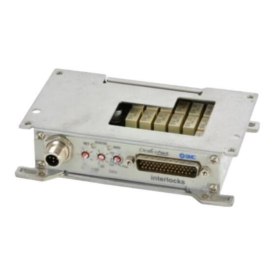
3 Name and function of parts
EX160-SDN2
No.
Part
Description
1
Mounting hole
Holes to mount the SI unit (4 positions).
®
®
DeviceNet
Connector for DeviceNet
(M12 5-pin plug,
2
connector
A-coded).
LED's to indicate Bus status and SI unit
3
LED display
status.
Interlock
Connector for external interlock circuit
4
connector
(44-pin D-sub plug connector).
Switches for setting of node address and
5
Switches
operating mode.
4 Installation
4.1 Mounting
Warning
• Do not install the product unless the safety instructions have been read
and understood.
• Applicable valve series: VQ1000.
Caution
• Be sure to turn OFF the power.
• Mount the SI unit using the 4 mounting holes in the base using M4
screws. Tightening torque must be 1.3 to 1.7 N•m.
4.2 Environment
Warning
• Do not use in an environment where corrosive gases, chemicals, salt
water or steam are present.
• Do not use in an explosive atmosphere.
• Do not expose to direct sunlight. Use a suitable protective cover.
• Do not install in a location subject to vibration or impact in excess of
the product's specifications.
• Do not mount in a location exposed to radiant heat that would result in
temperatures in excess of the product's specifications.
5 Wiring
5.1 Communication Connector
• Select the appropriate cable (SMC part number PCA-1557633 or
EX500-AC050-DN) to mate with the connector on the SI unit.
• The bus connector layout for DeviceNet
®
is as follows.
Connector: M12 5-pin plug, A-coded
No.
Signal
Description
1
DRAIN
Drain / Shield
2
V+
Power supply + for DeviceNet
3
V-
Power supply - for DeviceNet
4
CAN_H
CAN_H bus line (dominant high)
5
CAN_L
CAN_L bus line (dominant low)
5.2 Bus Terminator
• A bus termination resistor is required at both ends of the DeviceNet
trunk line.
The specification of the terminating resistor is 121 Ω ±1%, 1/4 W.
5.3 Interlock connector
• The interlock connector pin allocation is as shown below.
Interlock connector: 44-pin D-sub plug connector
Description
Pin assignment
Valve
Solenoid
Output
Common
Enable
Force
station
No.
channel
1A
0
13
28
1
1B
1
12
27
2A
2
11
26
2
2B
3
10
25
3A
4
9
24
3
3B
5
8
23
4A
6
7
22
4
4B
7
6
21
5A
8
5
20
5
5B
9
4
19
6A
10
31
32
6
6B
11
3
18
7A
12
15
30
7
7B
13
2
17
8A
14
14
29
8
8B
15
1
16
43, 44
• Pin numbers 33 to 42 are not used (reserved).
• The power supply for solenoid valves should be supplied using the
connector pins given above.
• The power supply for the SI unit operation is isolated. Be sure to supply
power separately using the M12 5-pin communication connector.
Either single-source power supplies or two different power supplies
can be used.
5.4 Ground Connection
• Connect the product to ground using a mounting hole screw.
Individual grounding should be provided close to the product.
Resistance to ground should be 100 ohms or less.
Tightening torque for the M4 screw is 1.3 to 1.7 N•m.
Page 1 of 2
®
®
®
(0 V)
Advertisement

Related Manuals for SMC Networks EX160-SDN2

Summary of Contents for SMC Networks EX160-SDN2
- Page 1 • Connect the product to ground using a mounting hole screw. Individual grounding should be provided close to the product. * Although EX160-SDN2 does not have any input channels. Resistance to ground should be 100 ohms or less. 4.2 Environment Tightening torque for the M4 screw is 1.3 to 1.7 N•m.
- Page 2 EX160-TF2Z164EN 6 Setting 7 LED display 6.1 Switch Settings • The switches should only be set with the power supply turned OFF. • Set the switches with a small flat blade screwdriver. • Set the switches before use. • Set the DeviceNet ®...
Need help?
Do you have a question about the EX160-SDN2 and is the answer not in the manual?
Questions and answers