
Related Manuals for Mitsubishi Electric EHWT17D-MHEDW


Summary of Contents for Mitsubishi Electric EHWT17D-MHEDW
- Page 1 Water to Water Heat Pump EHWT17D-MHEDW INSTALLATION MANUAL FOR INSTALLER English For safe and correct use, read this manual before installing the heat pump unit, which is installed indoors.
-
Page 2: Table Of Contents
Contents For safe and correct use, read this manual before installing the heat pump unit. 1. Safety Notices ............2 2. Introduction ............... 8 3. Technical Information ..........8 4. Installation............... 15 4.1 Location .............. 15 4.2 Water/Ambient Loop Quality and System Preparation ........ -
Page 3: Safety Notices
This installation manual along with the user manual should be left with the product after installation for future reference. Mitsubishi Electric is not responsible for the failure of locally-supplied parts. • Be sure to perform periodical maintenance. - Page 4 Safety Notices WARNING Mechanical The heat pump unit must not be installed, disassembled, relocated, al- tered or repaired by the user. Ask an authorised installer or technician. If the unit is installed improperly or modified after installation, water leak- age, electric shock or fire may result. The heat pump unit should be positioned on a hard level surface capable of supporting its filled weight to prevent excessive sound or vibration.
- Page 5 Safety Notices WARNING When installing, relocating, or servicing the heat pump unit, use tools and pipe components specifically made for use with R32 refrigerant and use only the specified refrigerant (R32) to charge the refrigerant lines. Do not mix it with any other refrigerant and do not allow air to remain in the lines.
- Page 6 Safety Notices WARNING Brine The selection of the brine MUST be in accordance with the applicable leg- islation. Take sufficient precautions in case of brine leakage. If brine leaks, venti- late the area immediately and contact your local dealer. The ambient temperature inside the unit can get much higher than that of the room, e.g.
- Page 7 Safety Notices CAUTION Use clean water that meets local quality standards on the primary circuit and ambient loop (When not using Brine). The heat pump unit should be located indoors to minimise heat loss. Remove as much air as possible from the primary and DHW circuits Refrigerant leakage may cause suffocation.
- Page 8 Safety Notices CAUTION Use circuit breakers (ground fault interrupter, isolating switch (+B fuse), and molded case circuit breaker) with the specified capacity. If the circuit breaker capacity is larger than the specified capacity, breakdown or fire may result. Tools (for R32) Gauge manifold Flare tool Charge hose...
-
Page 9: Introduction
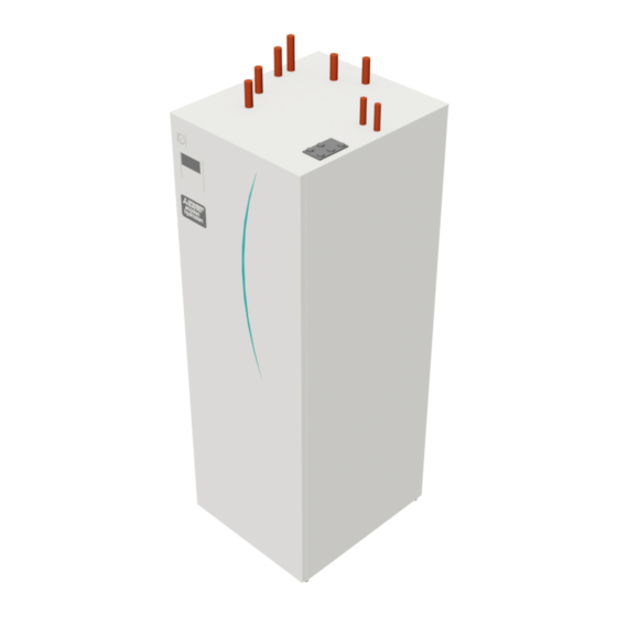
The target readers of this manual are competent heating, plumbing and/or refrigeration engineers who have at- tended and passed the requisite Mitsubishi Electric product training and have appropriate qualifications for installation of an unvented hot water heat pump unit specific to their country. - Page 10 Technical Information Component Parts <Overall> Part name DHW outlet pipe Cold water inlet pipe Water pipe (Space heating return connection (to heat pump)) Water pipe (Space heating flow connection (from heat pump)) Water/Brine pipe (Ambient loop return connection (to heat pump)) Water/Brine pipe (Ambient loop flow connection (from heat pump)) Control and electrical box Main remote controller...
- Page 11 Technical Information <Unit: mm> Technical Drawings 301.6 376.3 460.6 471.5 505.6 550.6 <TOP> HANDLE MANOMETER MAIN CONTROLLER TERMINAL BLOCK TEMPERATURE &PRESSURE RELIEF VALVE FRONT PANEL HANDLE HANDLE <BACK> <LEFT SIDE> <FRONT> <RIGHT SIDE> Letter Pipe description Connection size/type DHW outlet connection 22 mm/Compression Cold water inlet connection 22 mm/Compression...
- Page 12 Model name EHWT17D-MHEDW 230V 50Hz, length 460 mm. Maximum supply pressure to the pressure reducing valve 16 bar Use only Mitsubishi Electric service Operating pressure (Sanitary side) 3.5 bar parts as a direct replacement. Expansion vessel charge setting pressure (Sanitary side) 3.5 bar...
- Page 13 Technical Information Local system 1 1-zone temperature control Zone1 Zone1 2-zone temperature control 1-zone temperature control with boiler Zone1 Zone1 Zone2 1-zone temperature control 2-zone temperature control with boiler (2-zone valve ON/OFF control) Zone1 Zone1 Zone2 Zone2 1. Zone1 heat emitters (e.g. radiator, fan coil unit) (local supply) 10.
- Page 14 Technical Information Local system 2 1. Air to Water Heat Pump 2. Header 3. Buffer Tank 4. Central plate Heat source / Heat pump 5. Pump 6. Valve 7. Heat exchanger...
- Page 15 Pump 2 Pump 3 heater When additional pumps supplied ***(factory fitted locally are connected as Pump 2/3, EHWT17D-MHEDW 3 kW pump) change setting according to specs of the pumps. <Table 3.4> *1 "***" displayed in the energy monitor setting mode means the factory fitted pump is connected as Pump 1 so that the input is auto- matically calculated.
-
Page 16: Installation
Installation <Preparation before the installation and service> ● Prepare the proper tools. ● Prepare the proper protection. ● Allow parts to cool before attempting any maintenance. ● Provide adequate ventilation. ● After stopping the operation of the system, turn off the power-supply breaker and remove the power plug. ●... - Page 17 Installation Room thermostat Ambient temperature thermistor (TH7) If fitting a new room thermostat for this system; Please install the ambient temperature thermistor (TH7) in a place where external influences such as wind and sunlight are mini- • Position it out of direct sunlight and draughts mized.
- Page 18 Installation 4. Pull the MODULE BOX out by using the MODULE HANDLES Frame Module handles 5. After pulling MODULE BOX out Fit the cap or plastic bag etc. (local supply) on flexible pipes. Please bundle the wires during transportation and secure them with band etc.
-
Page 19: Water/Ambient Loop Quality
Installation 4.2 Water/Ambient Loop Quality and System Preparation <Water> <Ambient loop> General General • The water in both primary and sanitary circuit should be clean • The water in both primary and sanitary circuit should be clean and with pH value of 6.5-8.0 and with pH value of 6.5-8.0 •... -
Page 20: Water Pipe Work
Installation 4.3 Water Pipe Work Hot Water Pipework Pipework Connections Connections to the heat pump unit should be made using the The heat pump unit is UNVENTED. When installing un- 22 mm or 28 mm compression as appropriate. vented hot water systems building regulations part G3 (Eng- When connecting DHW pipes using compression fittings, insert land and Wales), P3 (Scotland) and P5 (Northern Ireland) copper liner for DHW pipe (accessory parts) into the pipes and... - Page 21 Installation Sizing Expansion Vessels Expansion vessel volume must fit the local system water volume. Expansion vessel sizing To size an expansion vessel for the heating circuit the following formula and graph can be used. When the necessary expansion vessel volume exceeds the volume of an built-in expansion vessel, install an additional expansion vessel so that the sum of the volumes of the expansion vessels exceeds the necessary expansion vessel volume.
-
Page 22: Ambient Loop Pipe Work
Installation 4.4 Ambient Loop Pipe Work Pipework Connections How to install PICV (Pressure Independent Connections to the heat pump unit should be made using the Control Valve) 22 mm compression as appropriate. PICV should be installed on the Ambient loop pipe in order to When connecting Ambient Loop pipes using compression balance water or brine in Ambient loop. - Page 23 Installation Filling the System (Ambient loop) 1. Check and charge expansion vessel. If expansion vessel is used, close the valve under the expansion vessel. 2. Check all connections including factory fitted ones are tight. 3. If you use filling pump, Connect the filling pump and return line on the ambient loop system's filler connector.
-
Page 24: Safety Device Discharge Arrangements (G3)
Installation 4.5 Safety Device Discharge Arrangements (G3) i. Ideally below a fixed grating and above the water seal in a trapped gully. The following instructions are a requirement of UK Building Regulations ii. Downward discharges at low level; i.e. up to 100 mm above external surfaces and must be adhered to. -
Page 25: Electrical Connection
Installation 4.6 Electrical Connection A Locally supplied wiring should be inserted through the inlets situ- ated on the top of the heat pump unit. (Refer to <Table 3.3>.) All electrical work should be carried out by a suitably qualified B Wiring should be fed down the back right hand side of the technician. - Page 26 Installation Affix label A that is included with the manuals near each wiring diagram for heat pump units. Wiring circuit Earth leak- breaker age circuit N.F. breaker Isolating Power supply *1 *2 switch ~/N 230 V 50 Hz To control board ECB2 Wiring circuit immersion heater...
-
Page 27: System Set Up
System Set Up 5.1 FTC 5.1.1 DIP Switch Function Located on the FTC printed circuit board are 6 sets of small white switches known as DIP switches. The DIP switch number is printed on the circuit board next to the relevant switches. The word ON is printed on the circuit board and on the DIP switch block itself. - Page 28 System Set Up 5.1.2 Connecting inputs/outputs CN01 TBO.1 (BK) CNP1 (WH) CN3C CNP4 TBO.2 (BU) (RD) LED1 Wiring specification and local supply parts CNPWM (WH) CNV1 Item Name Model and specifications CN851 TBO.3 (WH) (BK) Signal input Signal input Use sheathed vinyl coated cord or cable. CNRF function wire...
- Page 29 System Set Up Thermistor inputs Name Terminal block Connector Item Optional part model — CN20 Thermistor (Room temp.) (Option) PAC-SE41TS-E — CN21 Thermistor (Ref. liquid temp.) — THW1 — CNW12 1-2 Thermistor (Flow water temp.) — THW2 — CNW12 3-4 Thermistor (Return water temp.) —...
- Page 30 System Set Up Outputs Terminal Max. total Name Connector Item Signal/Max current block current OUT1 TBO.1 1-2 CNP1 Water circulation pump 1 output (Space heating & DHW) 230V AC 0.6A Max. OUT2 TBO.1 3-4 — Water circulation pump 2 output (Space heating for Zone1) 230V AC 1.0A Max.
- Page 31 System Set Up 5.1.3 Wiring for 2-zone temperature control Connect the pipe work and locally supplied parts according to the relevant circuit diagram shown “Local system” in Section 3, of this manual. <Mixing valve> Connect the signal line to open Port A (hot water inlet port) to TBO.
- Page 32 This facility is accessed via password protected service menus. To provide the best efficiency Mitsubishi Electric recommends using automatic adaptation function based on room temperature. To use this function a room thermistor needs to be present in a main living area. This can be done in a number of ways the most conveni- ent are detailed below.
- Page 33 System Set Up 1-zone temperature control Control option A Wireless remote controller Wireless receiver This option features the main remote controller and the Mitsubishi (option) (option) Electric wireless remote controller. The wireless remote controller is used to monitor room temperature and can be used to make changes to the space heating settings, boost DHW and switch to 20.0°C holiday mode without having to directly use the main remote...
- Page 34 Control option A Wireless receiver Wireless remote (option) This option features the main remote controller, the Mitsubishi Electric controller (option) wireless remote controller and a locally supplied thermostat. The wireless remote controller is used to monitor the Zone1 room tempera- ture and the thermostat is used to monitor the Zone2 room temperature.
- Page 35 System Set Up Control option D This option features the locally supplied thermostats wired to FTC. The thermo- stats are individually allocated to Zone1 and Zone2. The thermostats are used Room temperature to set each maximum temperature for heating Zone1 and Zone2 rooms. Any thermostat changes to DHW must be made using the main remote controller mounted on (local supply)
- Page 36 5.1.8 Using SD memory card (9) FTC supports FAT fi le system but not NTFS fi le system. (10) Mitsubishi Electric is not liable for any damages, in whole The heat pump unit is equipped with an SD memory card inter- or in part, including failure of writing to an SD memory face in FTC.
- Page 37 System Set Up 5.1.9 Main remote controller <Main remote controller parts> Letter Name Function Screen Screen in which all information is displayed. Menu Access to system settings for initial set up and modifications. Back Return to previous menu. Confirm Used to select or save. (Enter key) Power/ If system is switched off pressing once will turn system Holiday...
- Page 38 System Set Up [Initial settings wizard] When the main remote controller is switched on for the first time, the screen automatically goes to Language setting screen, Date/ Time setting screen and Main settings menu screen in order. Enter the desired number using the function keys and press CONFIRM. Note: <[HEATER CAPACITY RESTRICTION]>* This setting restricts the capacity of booster heater (if fitted).
- Page 39 System Set Up <Main Remote Controller Menu Tree> Unrestricted access Initial Installer only Main screen * Short press for 1 Zone system. Information Long press Option Forced DHW ON ( )/OFF ON ( )/Prohibited ( )/Timer ( ) Heating ON ( )/Prohibited ( )/Timer ( ) Menu Energy monitor Consumed electrical energy...
- Page 40 System Set Up <Continued from the previous page.> Unrestricted access <Main Remote Controller Menu Tree> Installer only Initial Main screen Main Long press menu yyyy/mm/dd/hh:mm Date/Time Menu Initial Language EN/FR/DE/SV/ES/IT/DA/NL/FI/NO/PT/BG/PL/CZ/RU/TR/SL settings Summer time OFF/ON Temp. display OFF/Room/Tank/Room&Tank Contact number TH1/Main RC/ Sensor Time display hh:mm/hh:mm AM/AM hh:mm...
- Page 41 System Set Up <Continued from the previous page.> Unrestricted access <Main Remote Controller Menu Tree> Installer only Initial Long press Main Main screen menu ON/OFF Operation Smart grid ready settings Target temp. Service Menu Password ON/OFF protected Heating Target temp. ON/OFF(Heating) Pump cycles Interval...
- Page 42 System Set Up [Service Menu] The service menu provides functions for use by installer or service engineer. It is NOT intended the home owner alters settings within this menu. It is for this reason password protection is required to prevent unauthorised access to the service settings. The factory default password is "0000".
- Page 43 System Set Up <[Auxiliary settings]> This function is used to set the parameters for any auxiliary parts used in the system Menu subtitle Function/ Description Economy settings Water pump stops automatically a specified period of time from for pump when operation is finished. Delay Time before pump switches off*1 Electric heater...
- Page 44 System Set Up <[Operation settings]> [Heating operation] This function allows operational setting of flow temperature range from the heat pump unit and also the time interval at which the FTC collects and processes data for the auto adaptation mode. Menu subtitle Function Range Unit...
- Page 45 System Set Up Target flow temp. [Floor dry up function] (°C ) The Floor dry up function automatically changes the target hot water temperature in stages to gradually dry concrete when this particular type of underfloor heating system is installed. Upon completion of the operation the system stops all the op- erations except the Freeze stat.
- Page 46 System Set Up 5.2 C.B. 5.2.1 DIP Switch Function Located on the C.B. printed circuit board are 7 sets of small white switches known as DIP switches. The DIP switch number is printed on the circuit board next to the relevant switches. The word ON is printed on the circuit board and on the DIP switch block itself. To move the switch you will need to use a pin or the corner of a thin metal ruler or similar.
-
Page 47: Commissioning
System Set Up 5.2.2 Connecting inputs/outputs Inputs/Outputs Name Connector Item TB-U/V/W Motor for compressor (Mediate Power board) High Pressure switch 63HS 63HS High Pressure Sensor Flow switch (Ambient loop) Thermistor (Ref. liquid temp.) Thermistor (Discharge temp.) TH7/6 Thermistor (Outdoor temp.) Thermistor (Heat sink temp.) TH32 TH32... -
Page 48: Service And Maintenance
Service and Maintenance Error Codes (FTC) Code Error Action Flow rate may be reduced. Check for; • Water leakage Circulation water temperature overheat protec- • Strainer blockage tion • Water circulation pump function (Error code may display during filling of primary circuit, complete filling and reset error code.) DHW tank water temperature overheat protec- Check the immersion heater and it’s contactor. - Page 49 Service and Maintenance Error Codes (C.B.) Code Error Cause Action 1 No voltage is supplied to terminal 1 Check following items. block (TB1) of heat pump unit. a) Power supply breaker a) Power supply breaker is turned off. b) Connection of power supply terminal b) Contact failure or disconnection of block (TB1) power supply terminal...
- Page 50 Service and Maintenance Code Error Cause Action High discharge temperature 1 Overheated compressor operation 1 Check intake superheat. (1) Abnormal if TH4 exceeds caused by shortage of refrigerant Check leakage of refrigerant. 125°C or 110°C continuously Charge additional refrigerant. for 5 minutes. 2 Defective thermistor 23 Turn the power off and check if U3 is (2) Abnormal if discharge super-...
- Page 51 Service and Maintenance Code Error Cause Action Too low superheat due to low 1 Disconnection or loose connection 12 Check the installation conditions of dis- discharge temperature of discharge temperature thermistor charge temperature thermistor (TH4). Abnormal if discharge superheat is (TH4) continuously detected less than or 2 Defective holder of discharge tempera-...
- Page 52 It is essential that the heat pump is serviced at least once a year by a qualified individual. Any required parts should be purchased from Mitsubishi Electric. NEVER bypass safety devices or operate the unit without them being fully operational. For more details, refer to service handbook.
- Page 53 Service and Maintenance Engineers Forms Should settings be changed from default, please enter and record new setting in ‘Field Setting’ column. This will ease resetting in the future should the system use change or the circuit board need to be replaced. Commissioning/Field settings record sheet Default Field...
- Page 54 Service and Maintenance Engineers Forms Commissioning/Field settings record sheet (continued from the previous page) Default Field Main remote controller screen Parameters Notes setting setting Setting Service Thermistor THW1 −10°C to +10°C 0°C adjustment menu THW2 −10°C to +10°C 0°C THW5A −10°C to +10°C 0°C THW5B...
- Page 55 Service and Maintenance Engineers Forms Commissioning/Field settings record sheet (continued from the previous page) Default Field Main remote controller screen Parameters Notes setting setting Setting Service Operation Smart grid On/Off menu settings ready Target temp (+1 to +20°C) / -- (Non active) Heating On/Off Switch-on recommendation (20 to 60°C) 50°C...
-
Page 56: Supplementary Information
*4 The “Hybrid” automatically switches heat sources between Heat pump (and Electric heater) and boiler. Product fiche of temperature control (a) Supplier's name: MITSUBISHI ELECTRIC CORPORATION (b) Supplier's model identifier: PAR-WT50R-E and PAR-WR51R-E (c) The class of the temperature control:... - Page 58 EU-OVERENSSTEMMELSESERKLÆRING EU-CONFORMITEITSVERKLARING MITSUBISHI ELECTRIC AIR CONDITIONING SYSTEMS EUROPE LTD. NETTLEHILL ROAD, HOUSTOUN INDUSTRIAL ESTATE, LIVINGSTON, EH54 5EQ, SCOTLAND, UNITED KINGDOM hereby declares under its sole responsibility that the air conditioner(s) and heat pump(s) for use in residential, commercial, and light-industrial environments described below: intygar härmed att luftkonditioneringarna och värmepumparna som beskrivs nedan för användning i bostäder, kommersiella miljöer och lätta industriella miljöer:...
- Page 59 UK DECLARATION OF CONFORMITY MITSUBISHI ELECTRIC AIR CONDITIONING SYSTEMS EUROPE LTD. NETTLEHILL ROAD, HOUSTOUN INDUSTRIAL ESTATE, LIVINGSTON, EH54 5EQ, SCOTLAND, UNITED KINGDOM hereby declares under its sole responsibility that the air conditioner(s) and heat pump(s) for use in residential, commercial, and light-industrial environments described below:...
- Page 60 This product is designed and intended for use in the residential, commercial and light-industrial environment. Importer: Mitsubishi Electric Europe B.V. Capronilaan 46, 1119 NS, Schiphol Rijk, The Netherlands French Branch 2, Rue De L’Union, 92565 RUEIL MAISON Cedex German Branch...
Need help?
Do you have a question about the EHWT17D-MHEDW and is the answer not in the manual?
Questions and answers