Table of Contents
Advertisement
Advertisement
Table of Contents

Related Manuals for Baby Lock PRO BL8800


Summary of Contents for Baby Lock PRO BL8800
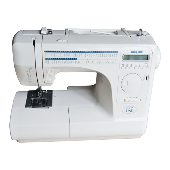
- Page 1 MODEL BL8800 SERVICE MANUAL...
-
Page 2: Table Of Contents
TABLE OF CONTENTS A.REMOVING THE FRONT COVER ......2 B. REPLACING THE FRONT COVER ......4 1. HEIGHT OF NEEDLE BAR ........5 2. GAP BETWEEN NEEDLE AND HOOK ..... 6 3. TIMING OF THE HOOK ..........7 4. HEIGHT OF THE FEED DOG ........8 5. -
Page 3: A.removing The Front Cover
A.REMOVING THE FRONT COVER fig. A-2 1. Remove the set screw (a) and the light cover. (fig. A-1) 2. Remove the left side screw (b) inside the thread take up lever cover. (fig. A-2) fig. A-1 fig. A-3 3. Remove the screw (c) located on the backside of machine, above the spool pin. - Page 4 6. Stand up the machine. fig A-6 The terminal cover will come out. Insert the screwdriver into the hole of machine from backside. Hook the tip of driver into the groove of forward- reverse adjusting knob (f). (fig A-6) Terminal Slide them to the left and remove the knob.
-
Page 5: Replacing The
B. REPLACING THE FRONT fig. B-1 COVER 1. Lower the presser foot lifter (k). Turn the hand wheel toward you until the thread take- up lever (l) rises to its highest point. (fig. B-1) 2. Connect the two cord connectors (i, j) from front cover to the CPU circuit board on machine. -
Page 6: Height Of Needle Bar
1. HEIGHT OF NEEDLE BAR fig. 1-1 Height of needle bar could be the cause for stitches to skip. Check as the following procedures. 1. Set the pattern number at “2” which is straight stitch on center needle position. 2. Raise the needle bar to its highest point by turning the handwheel toward you. -
Page 7: Gap Between Needle And Hook
2. GAP BETWEEN NEEDLE AND fig. 2-1 HOOK If the needle hits aginst the hook, it may be the cause of needle and thread breakages. If the gap between needle and hook is too big, it will cause to skip stitches. Check and adjust as follows: Prior to make this adjustment, check that the needle is not bent and the needle is inserted correctly. -
Page 8: Timing Of The Hook
3. TIMING OF THE HOOK fig. 3-1 Prior to making this adjustmetnt, be sure that the needle bar is set at the correct height. (See sec. 1) Check the timing of hook as follows: 1. Remove the needle plate and bobbin holder. (See sec. 1-2) 2. -
Page 9: Height Of The Feed Dog
4. HEIGHT OF THE FEED DOG fig. 4-1 If the feed dog does not come up over the needle plate enough, it will result in insufficient and/or uneven feed of fabrics. The feed dog should come up over the needle plate +0.05 mm. -
Page 10: Timing Of The Feed Motion
6. TIMING OF THE FEED MOTION fig. 6-1 If the feed motion is too fast of foo slow, it will be the cause of fabfic puckers or needle breakage. Check and adjust the feed timing as follows: 1. Tilt the machine backward and remove the bed lid by removing the screw and sliding it to the left. -
Page 11: Adjusting The Forward And Reverse Stitch
7. ADJUSTING THE FORWARD fig. 7-1 AND REVERSE STITCH When stretch stitch sewing, the lengths of the forward and reverse stitches should be the same. check as follows: 1. Set the forward-reverse adjusting knob to the center “-” mark. 2. Turn on the power switch with pressing the both of fig. -
Page 12: Height And Direction Of Presser Foot
9. HEIGHT AND DIRECTION OF fig. 9 PRESSER FOOT The height of the presser foot from the needle plate should be 5.5 mm when it is lifted up. (fig. 9) The presser foot should be facing frontward (the edge of foot is parallel with the feed dog slot on needle plate). -
Page 13: Zigzag Timing • Needle Stop Position
11. ZIGZAG TIMING • NEEDLE fig. 11 View from lowerside STOP POSITION The zigzag timing and the needle stop position when start/stop switch is pressed are controlled by the computer system. However, the needle bar position (upper shaft revolution angle) is detected by the sensor slit. -
Page 14: Backlash Of Hook Gear
14. BACKLASH OF HOOK GEAR fig. 14-1 If there is too much play on the hook gear on the turning direction, it may be the cause for machine not to sew properly and/or making excessive sewing noise. 1. Remove the needle plate and bobbin holder. 2. -
Page 15: Locating The Deffected Electrical Part
LOCATING THE DEFFECTED fig. I ELECTRICAL PART The self-diagnostic program This machine is provided with the self-diagnostic program for electrical parts. If the machine does not function normally, although the mechanical setting has been completed, check the electrical parts by this program. TO RUN THE SELF-DIAGNOSTIC PROGRAM fig. -
Page 16: Condition Of Switches And Sensors
b. Condition of switches and Buttonhole lever switch -Front Buttonhole lever switch -Back sensors Stop sensor Timing sensor The condition of each switch and sensor is indicated as Speed sensor follows. BH f: Buttonhole lever switch -Front 1=Neutral 0=Lever is pushed. BH b: Buttonhole lever switch -Back 1=Neutral 0=Lever is pulled. -
Page 17: B-1. Adjustment For Buttonhole Lever Position
b-1. Adjustment for buttonhole fig. b-1a lever position If the machine does not sew even with the buttonhole lever all the way down, it means that the buttonhole lever is not positioned properly. Also, if the buttonhole lever is not positioned properly, the machine will sew buttonhole as fig. -
Page 18: Phase Of Feed Pulse Motor
c. Phase of feed pulse motor When you have selected this mode, feed pulse motor will move slightly and stop at the position which the lever of gear intercept the feed sensor. Normally, the number 2 or 4 or 6 will appear on the LCD. If it was not so, loosen the screw of gear and rotate it slightly. -
Page 19: Trouble Shooting Of Electrical Parts
- 18 -... - Page 20 - 19 -...
Need help?
Do you have a question about the PRO BL8800 and is the answer not in the manual?
Questions and answers