Table of Contents
Advertisement
Quick Links
Advertisement
Table of Contents

Related Manuals for Orthofab oasis


Summary of Contents for Orthofab oasis
- Page 1 USER’S MANUAL Inc. All rights reserved 01190-0-00_rev.20211029...
- Page 2 . Always consult a health care professional for any modifications to your wheelchair. Please read the entire manual describing the control system of your Oasis electrically powered wheelchair before first use, along with the battery charger manual. They are provided for your safety. Inc. All rights reserved...
- Page 3 As Quebec’s only manufacturer of manual and electrically powered and tilt wheelchairs, is proud to offer high-quality wheelchairs, adapted to your needs and to your seating comfort, and we thank you for selecting one of our products. products comply with Quebec standard BNQ 6645-001 (2019), which specifies technical and documentary requirements for manufacturers of mobility devices.
-
Page 4: Table Of Contents
TABLE OF CONTENTS SAFETY RULES ..............................6 ............................... 6 ENERAL NFORMATION 1.1.1 Before you hit the road ................................6 1.1.2 Getting around in a wheelchair .............................. 7 1.1.3 Transferring ................................... 8 1.1.4 Miscellaneous handling ................................. 8 1.1.5 Component cleaning and maintenance ..........................9 ............................ - Page 5 TABLE OF CONTENTS 4.11.2 Removability ..................................42 4.11.3 Raising and lowering the leg support assembly ........................43 4.11.4 Motorized leg support ................................44 4.11.5 Foot support ..................................44 4.11.6 Lower leg support ................................45 4.12 ................................45 RM SUPPORT 4.12.1 T-shaped arm supports ...............................
-
Page 6: Safety Rules
• If you own an Oasis, make sure that the rubber protector under the joystick tip is in good condition (if not, have it repaired immediately). -
Page 7: Getting Around In A Wheelchair
• Reduce your speed in crowds and use your horn to signal your presence; • The Oasis can climb 50 mm obstacles; However, it is strongly recommended to avoid thresholds over 38 mm (1 ½ in.) as this could, depending on surface conditions, put your stability at risk;... -
Page 8: Transferring
1 SAFETY RULES • The Oasis wheelchair can negotiate slopes at low speed, with a maximum incline of 10°, external or internal, and a length of at least 3 metres, alone or with an assistant. The assistant must always be at the back of the wheelchair, whether ascending or descending, and should hold the back support posts;... -
Page 9: Component Cleaning And Maintenance
1 SAFETY RULES • Never submerge your wheelchair or leave it in the rain for a prolonged period; • Do not store your wheelchair in a damp or very cold place (this could cause serious damage); • If the occupant remains seated in a wheelchair while travelling in a road vehicle designed for transporting disabled persons, make sure that the occupant, driver and the vehicle owner respect all legislative, regulatory, policy, guideline and standard requirements, instructions and recommendations of all competent authorities;... -
Page 10: About Electromagnetic Energy
1 SAFETY RULES Special treatment: All upholstery from which foam cannot be removed (back support, lower leg support). Disinfection by hand. Using a cleaner, first wipe with a cloth, then apply a disinfectant, wait the required time, and wipe off. Not treatable: Electronic components (batteries, control box, etc.). - Page 11 1 SAFETY RULES • Turn the control box off as soon as it is safe to do so if the wheelchair is functioning erratically. • Report any such incident to ’s customer service department. Avoid using electronic devices when the electrically powered wheelchair is turned on.
-
Page 12: Recommended Use
With a 10 km/h motorized drive, they are the best option for outdoor use. Our Oasis line can be supplied with mounting points for using the wheelchair as a car seat, since it has undergone frontal impact testing in accordance with BNQ 6645-001/2019 standard. -
Page 13: Note To Assistants
The Oasis has a rear anti-tilt device (2 castors) that prevents accidental maneuvers. It is important for your safety to make sure they are always in place. -
Page 14: Stairs
DO NOT use any detachable components for leverage or use arm or foot supports to lift the wheelchair. When using an Oasis electrically powered wheelchair, avoid climbing stairs. If this is unavoidable, the occupant must be transported independently of the wheelchair, and batteries must be removed before the maneuver. -
Page 15: Transferring To Or From Another Seat
2 USE 2.2.7 T RANSFERRING TO OR FROM ANOTHER SEAT Turn the control box OFF before transferring (for electrically powered wheelchair). Before transferring, it is important to reduce the space between the two (2) transfer points. The front wheels must be turned toward the transfer point. -
Page 16: Technical Specifications
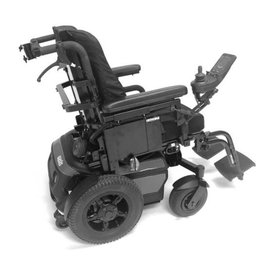
2 USE TECHNICAL SPECIFICATIONS 2.3 The Oasis electrically powered wheelchair Figure 1: Oasis power base (rear view). Figure 2: Oasis power base and seat Figure 3: Oasis power base and seat (front isometric view). (rear isometric view). Inc. All rights reserved... -
Page 17: Technical Information
2 USE TECHNICAL INFORMATION Manufacturer: Electrically powered wheelchairs – Adult Oasis PC (FMO-GM2-B-P2 – Compact multi-purpose unit PC-03 FMO-GM3-B-P2 FMO-GM2-A-P2 FMO-GM2-B-P2 Compact multi-purpose unit with Compact multi-purpose unit High performance multi-purpose unit one-piece central motorized leg 25-1/2" total width power base... -
Page 18: Installation And Adjustments
2 USE Removable "L" type and swing-away, height adjustable from 8 to 12 in. or from 10 to 14 in. 2-inch wide, 10-inch (short) or 14-inch (long) straight comfort padding Tubular, profile, and gel comfort pads also available Leg support assembly Swing-away and removable Angled release with spring-loaded swivel mechanism Knurled screw to lock leg support assembly release... -
Page 19: Rear Cover
2 USE After making any adjustments and before using the wheelchair, make sure that all hardware is tightly secured. Make sure all locking mechanisms are engaged before using the wheelchair. 4.1 Rear cover The rear cover must be removed to access the wheelchair’s mechanical and electrical components and to disconnect the batteries. -
Page 20: Replacing The Rear Cover
2 USE 3- Pull the top of the cover away from the top latch. (Figure 4-B). Figure 4-B 4- Gently pull the cover toward you. 5- Disconnect the cable from the rear lights (Figure 4-C). Figure 4-C 6- Disconnect the cable from the rear lights (Figure 4-C). 7- Place the cover in a safe location to avoid damaging the finish. -
Page 21: Adjusting The Suspension
Figure 5 Figure 5-B Suspension adjustment is done with an Orthofab suspension adjustment key (see Figures 5- A and 5-B). Clockwise rotation makes the suspension firmer, counter clockwise rotation makes the suspension softer. There is another tool that... -
Page 22: Adjusting The Axle Shock (Front) (Pc, Pc-03, Pcm)
2 USE Adjustment is easily done directly on the shock absorber attached to the wheelchair. Simply tighten or loosen the suspension according to the desired “L ”. Figure 5-E i. A ) (PC, PC-03, PCM) DJUSTING THE AXLE SHOCK FRONT For firm suspension, adjust the spring length (L ) to 2 3/4 in. -
Page 23: Wheels
4.3.1 I NSTALLING CASTOR WHEELS The Oasis wheelchair can accommodate different models of castors. Your choice of one or the other will depend on the environment where you will most frequently use your electrically powered wheelchair. The wheels are mounted on a double fork (see Figure 6). -
Page 24: Installing Drive Wheels
2 USE 4.3.2 I NSTALLING DRIVE WHEELS 1. Fit the wheel rim onto the wheel hub, aligning the four (4) holes on the rim with the four (4) holes on the wheel hub (see Figure 8-A). 2. Install the four (4) screws (A) with their lock washers (B), then tighten with a 1/2 in. or 13 mm socket wrench (see Figure 8-B). -
Page 25: Positioning The Seat
2 USE 4.4 Positioning the seat 4.4.1 C HANGING SEAT ANGLE AND HEIGHT The seat angle (called the tilt angle) can be adjusted for greater comfort. This adjustment is permanent. The tilt angle is increased or decreased by adjusting the floor-to-seat height. The adjustment range is 3 in. -
Page 26: Changing Seat Angle And Height (Adding +1 Or +2 In.)
2 USE You can also change the rear floor-to-seat height. This adjustment is made under the back cover. Using a ½ in. or 13 mm wrench, unscrew the (A) bolts and (B) nuts and adjust adjustment rod (C) with frame (D) and the base of bracket (E) to the desired height (see Figure 5-B). -
Page 27: Changing Seat Angle And Height (Adding +3 Or +4 In.)
2 USE SEAT WITH 45° TILT: REAR INTERFACE FRONT INTERFACE STIRRU Figure 5-D: 16 ½ in. and 17 ½ in. adjustment interface on a seat with a 45° tilt. FOR THE FRONT AND BACK: 1- Power off the control box and remove the seat plate and cushion. 2- Use a ½... -
Page 28: Batteries
2 USE NOTE: Floor-to-seat height modification interfaces should be installed by (2) people for ease of operation. Be careful not to damage the electrical cables during handling. The higher the seat is in relation to the ground, the more likely the wheelchair will tip backwards or sideways under heavy acceleration, sudden maneuvers or on slopes. - Page 29 2 USE 4.5.2.1 R EMOVING BATTERY BOXES 1. If the wheelchair is equipped with a tilt mechanism, set it at a slight angle to remove the batteries before disconnecting them. 2. Open the rear cover (section 4.1) and disconnect the power cables located at the rear of the frame (Figure 9) by pulling on the red straps.
- Page 30 4" of strap. The rest of the strap should extend to the back. 4. Pass the strap through the cover as shown. 5. Make sure that the connectors provided by Orthofab are properly bolted to the battery terminals. # Cover connectors with protective rubber caps.
- Page 31 2 USE Figure Battery cable Battery installation The length of the wires in the battery compartment was adjusted to avoid reversing the polarity of the batteries, so it is very important to make sure that the batteries are arranged as illustrated below. This measure is for your own safety and that of our users.
- Page 32 2 USE 4.5.2.2 R EPLACING THE BATTERY BOX NOTE: T HERE IS A LEFT AND A RIGHT BOX To differentiate the direction of the boxes, the power cable outlet (Figure 19) must always be located on the outside of the wheelchair. 1.
-
Page 33: Leg Support Assembly
2 USE 4.6 Leg support assembly 4.6.1 A DJUSTING THE LENGTH OF THE LEG SUPPORT ASSEMBLY 1- Using a 7/16 in. open-end wrench, completely unscrew the screw as shown in figure 20 below. This screw fits all models. 2- Adjust to the desired length. 3- Retighten the screw with a maximum torque of 100 lb-in, making sure to insert the washer. -
Page 34: Changing The Depth Of The Angle Adjustable Foot Support
2 USE 4.6.3 C HANGING THE DEPTH OF THE ANGLE ADJUSTABLE FOOT SUPPORT 1. Remove the two (2) Phillips screws (A) that hold the end piece (see Figure 21); 2. Pull the foot support out of the bracket; 3. Push in to the desired depth; 4. - Page 35 2 USE BRACKET FOOT SUPPORT TUBE Figure 22: Adjusting lower leg support height. Inc. All rights reserved...
-
Page 36: Adjusting Lower Leg Support Depth
4.7 Angle-adjustable back support You can adjust the standard back support tilt angle 4.7.1 C HANGING BACK SUPPORT ANGLE on the Oasis electrically powered wheelchair. Figure 24-A illustrates the mounting positions associated with the desired back support tilt angles. The back support tilt angle is the measured angle between the seat and the back support. -
Page 37: Changing Back Support Depth
2 USE 4.7.2 C HANGING BACK SUPPORT DEPTH Seat depth can be adjusted (see Figure 24-B). To do this: 1- Using a 7/16 in. open-end wrench, slightly loosen screws (A) and (B); 2- Slide the assembly to the desired position; 3- Make sure that both (2) sides are at the same distance from the front of the seat;... -
Page 38: Control Box Attachment
2 USE 4.8 Control box attachment To make any of the adjustments indicated below, you must switch off the wheelchair (joystick off) and disconnect the control box cable. 4.8.1 D EPTH ADJUSTMENT You can adjust the depth of the control box by moving the support. The support is attached under the arm support (left or right). -
Page 39: Adjusting The Lateral Position
2 USE 4.8.3 A DJUSTING THE LATERAL POSITION You can adjust the lateral position of the control box by adding a lateral adjustment bar (D) (see Figure 28). 1- Using a 3 mm Allen wrench, disconnect the cable from the control box (F) and remove the two (2) screws (A) that hold the control box to the retractable support (E). -
Page 40: Control System For 4 Motorized Accessories
Control box for 1 motorized accessory. The control system for 4 motorized accessories is directly connected to the R-Net controller. When the Oasis is controlled with emergency flashers and light control via the control box, you need a control system for 4 accessories with lights. -
Page 41: Leg Support Assembly
2 USE Do not modify any electrical components (fuse amperage, wire connections, etc.) of the electrically powered wheelchair. 4.11 Leg support assembly Depending on the options selected, the leg support assembly consists of the foot support, the heel brace and the lower leg support. It can be standard or compensating-elevating, to provide support for the entire leg by compensating for the distance of the foot support. -
Page 42: Removability
2 USE 4.11.2 R EMOVABILITY ’ 5.1.2.1 D ETACHING THE WHEELCHAIR S FOOT OR LEG SUPPORT 1- Retract the foot support (see previous section 4.11.1). 2- If the wheelchair is equipped with an elevating lower leg support assembly, disconnect the power to the leg support motor. The connector is located near the motor. 3- Lift the leg support assembly up and set it in a safe place. -
Page 43: Raising And Lowering The Leg Support Assembly
2 USE 4.11.3 R AISING AND LOWERING THE LEG SUPPORT ASSEMBLY 4.11.3.1 R AISING THE LEG SUPPORT 1- Pull the leg support up, using the plate support tube. 2- Move it to the desired position. PLATE SUPPORT TUBE Figure 31: Manual elevating leg support. 4.11.3.2 L OWERING THE LEG SUPPORT 1- Use the plate support tube to hold the leg support. -
Page 44: Motorized Leg Support
2 USE 4.11.4 M OTORIZED LEG SUPPORT 4.11.4.1 R EMOVING THE MOTORIZED LEG SUPPORT ASSEMBLY 1- When removing the leg support, make sure to disconnect the power connector (A) (see Figure 31-A). 2- When replacing the leg support, make sure to reconnect the power connector (A) (see Figure 31-A). -
Page 45: Lower Leg Support
Depending on requirements, lower leg supports are adjustable in angle, height, and depth. 4.12 Arm support Our Oasis electrically powered wheelchairs are available with "T", "U", or "L" arm support design. The choice depends on the occupant’s needs and wheelchair configuration. -
Page 46: U-Shaped Arm Supports
2 USE Note: Tightening the black clamping screw (A) eliminates any slack between the arm support and the base. DJUSTING THE HEIGHT OF THE ARM SUPPORT 1- Using an 8 mm open-end wrench and a 4 mm Allen wrench, slightly loosen the lock nut and screw (F) on the arm support side panel (H) (see Figure 33-A). -
Page 47: L-Shaped Arm Supports
2 USE EMOVABILITY 1- Following the procedure in Section 5.3.1, slightly retract the arm support from its front base (B) (see Figure 33-A). 2- Use a 1/8 in. hex key to loosen the screw (E) on the base (C). Lift the arm support assembly with the arm support pad (J) to slide it off the rear base (C). - Page 48 2 USE press outward. OPTIONAL CLOTHING GUARD 2- To close the arm support, turn it towards the wheelchair. It will lock itself by its own weight. Inc. All rights reserved...
-
Page 49: Reclining Back Support
2 USE 4.13 Reclining back support The wheelchair seat can be equipped with a pneumatic (manually operated) or electrical reclining back support. The reclining back support provides a change of position, while reducing the risk of shearing (stress under undesirable tension) for optimal comfort in the relaxation position. -
Page 50: Electric Mechanism
2 USE 4.13.2 E LECTRIC MECHANISM 4.13.2.1 R ECLINING THE BACK SUPPORT 1- If your wheelchair has one power accessory control, use the control box located on the side (right or left) of the wheelchair and pull the switch back (see Figure 34-B). If your wheelchair has more than one power accessory, or if your back support is controlled via a joystick, use the control box joystick (see the R-Net user manual). -
Page 51: Height And Depth Adjustable Head Support
2 USE 4.14 Height and depth adjustable head support 1- Turn the handle (A) to adjust the depth of the head support and turn the two handles (B) to adjust the height (see Figure 34-C). 2- After selecting the head support height position, adjust the retaining ring (C) on the head support anchor (D) for a better fit, and to indicate the position when replacing the head support. -
Page 52: Pelvic Positioning Belt
2 USE 4.15 Pelvic positioning belt Your wheelchair is equipped with a pelvic positioning belt. This is not an approved seat belt for transport in a motor vehicle or aircraft. The belt should fit snugly around the hips, to eliminate the possibility of slipping. FIXING POINTS (2X) PUSH... -
Page 53: Manually Releasing The Brakes
Always power off the control box before pushing the wheelchair in freewheel mode. The Oasis PC wheelchair is equipped with a mechanism that allows a person to push the wheelchair when it is not in use, or when the batteries are empty. Always power off the control box before manually pushing the wheelchair (see Figure 37). -
Page 54: Lights
Electrically powered wheelchairs and manual wheelchairs are equipped with optional reflective devices. There are two white reflective rings and two red strips available. 4.17.2 Lighting devices The Oasis PC electrically powered wheelchair is optionally equipped with: Inc. All rights reserved... - Page 55 2 USE 2 red lights on the rear cover 2 white headlights at the front The 4 positioning lights are activated by the switch on the side of the wheelchair arm support (see Figure 42). POSITIONING LIGHTS CONTROL SWITCH Figure 42: Positioning lights control switch. •...
-
Page 56: 45° Tilt Mechanism (Optional)
2 USE 4.18 + 45° tilt mechanism (optional) The 45° tilt mechanism should only be used when the wheelchair is on an even surface.. Before operating the 45° tilt mechanism, make sure there is adequate space above the occupant’s knees, behind the back support and above the foot supports. When using the tilt, keep your hands away from the seat. -
Page 57: Specialized Transit
4.19 Specialized transit 4.19.1 General warnings The Oasis electrically powered wheelchair line complies with BNQ 6645-001 and ISO 7176- 19 requirements. The wheelchair must face the road in a motor vehicle, and both lap and shoulder belts should restrain the occupant, as the model has been subjected to the frontal impact test. - Page 58 Section 1 – General information • The Oasis range model has been tested according to the 7176-19 standard, with specific configuration and components that comply with standard BNQ-6645-001/2019. When used as a seat in a motor vehicle, the wheelchair must be immobilized in a forward-facing position.
- Page 59 2 USE • Postural components should NOT be used as a restraint system. • The wheelchair weighs 129 kg in its test configuration. Accommodation assessment of wheelchair according to Annex D of ISO 7176-19 Criteria Assessment Ease of belt fitting Excellent Quality of belt fit Excellent...
- Page 60 2 USE The belt should pass over the occupant’s body and not over parts of the wheelchair, such as arm supports or wheels. The shoulder belt should fit snugly over the body through the midpoint of the shoulder and across the centre of the abdomen.
- Page 61 2 USE Make sure the belts are not twisted. They should be adjusted as tightly as possible, allowing for the comfort of the occupant. • Your seat belt is factory-fitted at and should not be modified/removed or ’s instructions. replaced without •...
- Page 62 2 USE Section 3 – Checks The following items should be inspected before using the wheelchair as a seat in a motor vehicle. Leg support anchor It is preferable to lock the leg support release to avoid accidental release during transport, or to prevent the leg support from being knocked off in an accident.
-
Page 63: Recharging The Batteries And Charger
2 USE 4.20 Recharging the batteries and charger Consult the safety instructions on page 8 and following pages. • Recharge the batteries in a ventilated area. • Do not smoke near the charger while the batteries are recharging. • Do not stay in the wheelchair while the batteries are recharging. The battery charger is designed for fast and safe recharging of the batteries for electrically powered wheelchairs. -
Page 64: Switch And Indicator Functions
2 USE Charge indicator Power indicator Connecting plug (24 VDC) and safety 4.20.2 S WITCH AND INDICATOR FUNCTIONS 5.11.2.1 P 5.11.2.2. C OWER INDICATOR HARGE INDICATOR The red indicator shows The other indicator shows when the POWER whether the battery charger is on or charger is in charging mode - yellow off. -
Page 65: Start-Up
2 USE 5.11.2.3. V OLTAGE SELECTOR The charger has an automatic internal voltage selector; it will select the voltage itself, depending on your location or country. North American standard is 110 volts. 4.20.3 S TART 1. Unroll the power cord (A) inside the cord winder behind the back support (see Figure 45-A). -
Page 66: Powering Off The Charger
2 USE Do not expose the charger to the elements. 4.20.4 P OWERING OFF THE CHARGER 1. Unplug the charger (110 VAC) plug (B) from the 110-volt socket (or 220 volts, depending on the region of use). 2. Rewind the power cord (A) into the cord winder behind the back support (see Figure 45-A). -
Page 67: Transporting The Wheelchair
2 USE 4.23 Transporting the wheelchair • Make sure to protect the control box when transporting the wheelchair. Pay close attention to the cables. • Do not lift the wheelchair by its detachable components (arm and foot supports, etc.). • Secure the wheelchair during transport to avoid movement. •... -
Page 68: Maintenance
3 MAINTENANCE 5 MAINTENANCE 5.1 Maintenance procedures Your wheelchair, like any other vehicle, will need proper maintenance for safe and efficient operation. Routine maintenance will extend the life and performance of your chair. Take your chair to a qualified dealer or authorized service centre once a year for thorough inspection and maintenance. -
Page 69: Cleaning
3 MAINTENANCE 5.3 Cleaning • Always keep the control box and joystick clean. • Do not use abrasives or solvents that can damage the surface finish of the cover and metal parts. Use a mild soap with a little water and a soft cloth. •... -
Page 70: Battery Cleaning
3 MAINTENANCE 5.4.4 B ATTERY CLEANING • To avoid contact between the two poles caused by dust or waste accumulation, clean the outside of the batteries with a little water and baking soda. This will extend battery life. • Remove any signs of oxidation. •... -
Page 71: Releasing The Brakes
3 MAINTENANCE 5.7 Releasing the brakes • Power off the control box. • Release the brakes (see Section 4.16). • Push the wheelchair: the wheelchair should be easy to push. • If not, consult a technician at an authorized service centre. •... -
Page 72: Troubleshooting Guide
4 TROUBLESHOOTING GUIDE 6 TROUBLESHOOTING GUIDE If any of the following problems are diagnosed, check the potential causes listed. If the suggested solutions do not solve the problem, consult a technician at an authorized service centre. Your wheelchair’s electronic control and charger manuals may also provide solutions. Control box lights do not illuminate;... - Page 73 4 TROUBLESHOOTING GUIDE The wheelchair does not maintain a straightforward trajectory when pushing the joystick fully forward. Possible causes Solutions Tire pressure is too low. Inflate to 35 psi. Ball bearings are damaged. Consult a technician at an authorized service centre.
-
Page 74: Charger Malfunction
4 TROUBLESHOOTING GUIDE 6.1 Charger malfunction If any of the following problems are diagnosed, check the potential causes listed. If the suggested solution does not solve the problem, consult a technician at an authorized service centre. 6.1.1 C HARGER LIGHTS DO NOT ILLUMINATE POSSIBLE CAUSES SOLUTIONS HE INPUT FUSE IS BURNT OUT... -
Page 75: Warranty
O RTHOFAB This is provided in lieu of any other written, implied, or statutory warranty. ORTHOFAB’s liability is limited to the repair or replacement of any part or component as set forth above. - Page 76 ORTHOFAB, nor to repairs and modifications not performed by an authorized O RTHOFAB distributor. The warranty shall be limited to the repair and, at ORTHOFAB’s absolute discretion, the replacement of defective material as provided herein. Except for the warranties set forth herein, O...
-
Page 77: Authorized Centres
AUTHORIZED CENTRES Technical Aids Services Addresses CIUSSS du Bas-Saint-Laurent 800, avenue Sanatorium 800, avenue Sanatorium Mont-Joli (Québec) G5H 3L6 Mont-Joli (Québec) G5H 3L6 CIUSSS du Saguenay-Lac-Saint-Jean 2230, rue de l'Hôpital 2230, rue de l'Hôpital Jonquière (Québec) G7X 7X2 Jonquière (Québec) G7X 7X2 CIUSSS de la Capitale-Nationale Site François Charron / section adultes 525, boulevard Wilfrid-Hamel Est... - Page 78 CISSS de l'Outaouais 135, boulevard Saint-Raymond 135, boulevard Saint-Raymond Gatineau (Québec) J8Y 6X7 Gatineau (Québec) J8Y 6X7 CISSS de l'Abitibi-Témiscamingue 622, 4e Rue Ouest CH SAT Amos Amos (Québec) J9T 2S2 622, 4e Rue Ouest 7, 9e Rue Amos (Québec) J9T 2S2 Rouyn-Noranda (Québec) J9X 2A9 CISSS de l'Abitibi-Témiscamingue 915, rue Germain...
- Page 79 Customer Service Centre 2160, De Celles Québec (Québec) G2C 1X8 (418) 847-5225 (800) 463-5293 Oasis 01190-0-00_rev.20211029 Inc. All rights reserved...
Need help?
Do you have a question about the oasis and is the answer not in the manual?
Questions and answers