Advertisement
Quick Links
Advertisement

Related Manuals for Wavecrest DTS-2070

Summary of Contents for Wavecrest DTS-2070
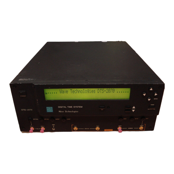
- Page 1 WAVECREST Corporation Calibration Procedure for the DTS-2070 Time Measurement System...
- Page 2 For this reason, any current WAVECREST product may differ in some respect from its published description but will always equal or exceed the original design specifications unless otherwise stated.
- Page 3 WAVECREST Corporation DTS-2070C ALIBRATION ROCEDURE FOR EASUREMENT YSTEM Equipment Required: Frequency counter with high stability time base (9½ digit resolution) Digital voltmeter (6½ digit resolution) Variable output power supply (Ø-6 VDC) 50 ohm SMA connectorized cables of equal length (approximately 1 meter) 5/64"...
- Page 4 WAVECREST Corporation (1-5) Using the hex wrench, remove the screws from the bottom. Store cover and screws in a safe place. (1-6) Turn DTS system over, so that the front panel is right side up. Then connect the AC power cord to the rear of the DTS. Ensure that the main DTS power switch and front panel standby switch are both off.
- Page 5 WAVECREST Corporation (2-6) Using the voltmeter, measure -5VDC at TP3 of the back plane. Verify the voltage is -5VDC ±0.05V. If adjustment is required, the -5VDC module closest to the DTS front panel must be adjusted at VOUT. (2-7) Using the voltmeter, measure -5VDC at the location shown in Figure 1B on the TMU470 board.
- Page 6 WAVECREST Corporation 100 MHz Oscillator Check (3-1) Connect one SMA cable to the l00 MHz reference clock output at the back of the unit. Connect the SMA cable to the frequency counter (50 ohm input) and verify the oscillator output is 100.0 MHz ±0.9 Hz.
- Page 7 WAVECREST Corporation Reference Voltage Operational Check (5-1) Using the voltmeter, set the power supply for each value shown in Table 1. Then remove the voltmeter and connect the power supply to the DTS CH1. Press the "FUNC" key to perform a pulse find operation. The displayed voltages at Menu #5 for CH1 should be between the values shown in Table 1.
- Page 8 WAVECREST Corporation (6-5) Press the BURST button on the front panel. Verify the "electrical length" of the cable delay line being measured (in picoseconds) is within ±10 psec of the calibrated length. (6-6) Set MEASUREMENT to OFF and remove the delay line.
- Page 9 End of Calibration Procedure If any display function does not appear to provide reasonable results, notify the WAVECREST Corporation factory for support at 1-800-733-7128. DTS-2070C Calibration Procedure (17 April 1998)
- Page 10 If you would like to be included in the distribution of new versions of this calibration procedure in the future, please indicate this to us by mailing this form back to Wavecrest Corp. at the address shown below, or fax it to the Director of Quality at (612) 831 - 4474.
- Page 11 WAVECREST Corporation WAVECREST Corporation World Headquarters West Coast Office: 7275 Bush Lake Road 1735 Technology Drive, Suite 400 Edina, MN 55439 San Jose, CA 95110 (612) 831-0030 (408) 436-9000 FAX: (612) 831-4474 FAX: (408) 436-9001 Toll Free: 1-800-733-7128 1-800-821-2272 www.wavecrestcorp.com...
Need help?
Do you have a question about the DTS-2070 and is the answer not in the manual?
Questions and answers