Advertisement
Table of Contents
PRECAUTIONS
Warning: Batteries produce explo-
sive gases, contain corrosive acid, and
supply levels of electrical current high
enough to cause burns. Therefore, to re-
duce the risk of personal injury when
working near a battery: Always shield
your eyes and avoid leaning over the
battery whenever possible; do not ex-
pose the battery to open flames or
sparks; do not allow the battery electro-
lyte to contact the eyes or the skin; flush
immediately and thoroughly any con-
tacted areas with water, and get medical
help.
Unless directed otherwise, the ignition
and start switch must be in the OFF or
LOCK position, and all electrical loads
must be OFF before servicing any electri-
cal component. Disconnect the battery
ground cable to prevent an electrical
spark should a tool or equipment come in
contact with an exposed electrical termi-
nal. Failure to follow these precautions
may result in personal injury and/or dam-
age to the vehicle or its components. For
vehicles equipped with OnStar® (UE1)
with Back Up Battery, the back up battery
is a redundant power supply to allow lim-
ited OnStar® functionality in the event of a
main vehicle battery power disruption to
the VCIM (OnStar® module). Do not dis-
connect the main vehicle battery or
remove the OnStar® fuse with the ignition
key in any position other than OFF.
Retained Accessory Power (RAP) should
be allowed to time out or be disabled (sim-
ply opening the driver door should disable
RAP) before disconnecting power. Dis-
connecting power to the OnStar® module
in any way while the ignition is ON or with
RAP activated may cause activation of the
OnStar® Back Up Battery (BUB) system
and will discharge and permanently dam-
age the BUB. Once the BUB is activated,
it will stay on until it has completely dis-
charged. The BUB is not rechargeable
and, once activated, the BUB must be
replaced.
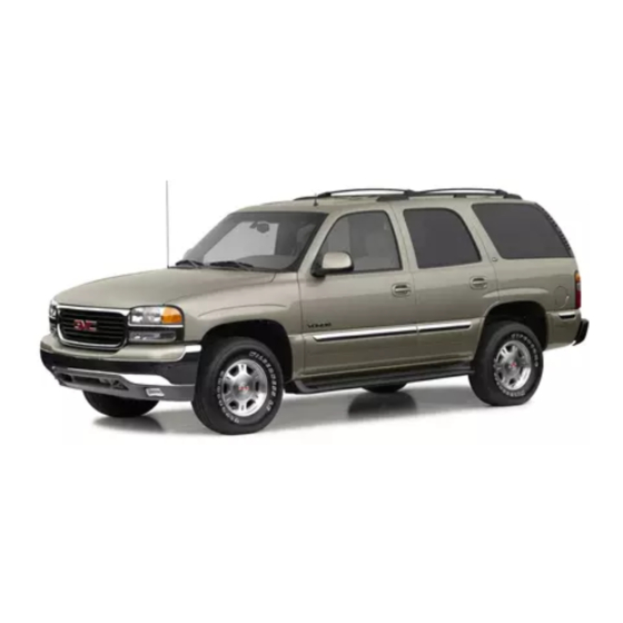
2002 YUKON
GMC
2002 Yukon
Fig. 1 Primary battery cable
removal
BATTERY
Primary
REMOVAL
1. Record radio anti-theft code and sta-
tion presets.
2. Turn off all lamps and accessories.
3. Turn ignition switch to OFF position.
4. Disconnect battery ground cable (6),
Fig. 1.
5. Open starter solenoid cable cover at
positive battery terminal, Fig. 1.
6. Loosen starter solenoid cable nut (5),
Fig. 1.
7. Remove starter solenoid cable from
positive battery terminal.
8. Remove righthand front fender rear
upper brace bolts and brace, Fig. 2.
9. Remove battery hold down retainer
bolt and retainer, Fig. 3.
10. Remove battery from battery tray.
INSTALLATION
Clean any existing corrosion from the
battery terminal and the battery cable end.
1. Install battery to battery tray.
2. Install battery hold down retainer and
bolt, Fig. 3. Torque bolt to 18 ft. lbs.
3. Install righthand front fender rear
upper brace and bolts, Fig. 2. Torque
bolts to 80 inch lbs.
4. Install starter solenoid cable to positive
battery terminal.
5. Install starter solenoid cable nut (5),
Fig. 1. Torque nut to 44 inch lbs.
6. Close starter solenoid cable cover at
positive battery terminal.
7. Install battery ground cable (6) to bat-
tery terminal, Fig. 1. Torque nut to 44
inch lbs.
8. Reset all preset and theft codes previ-
ously recorded to radio.
Auxiliary
REMOVAL
1. Record radio anti-theft code and sta-
BTY1200000000378
tion presets.
2. Turn off all lamps and accessories.
3. Turn ignition switch to OFF position.
4. Remove battery ground cable and bolt
from auxiliary battery, Fig. 4.
5. Open auxiliary battery positive cable
cap, Fig. 5.
6. Remove battery positive cable and bolt
from auxiliary battery.
7. Remove auxiliary battery hold down
retainer bolt and retainer, Fig. 6.
8. Remove auxiliary battery from battery
tray.
9. Remove battery insulator from auxilia-
ry battery.
INSTALLATION
Clean any existing corrosion from the
battery terminal bolt flange and the battery
cable end.
1. Install battery insulator to auxiliary bat-
tery, Fig. 6.
2. Install auxiliary battery to battery tray.
3. Install auxiliary battery hold down re-
tainer and bolt, then torque bolt to 18
ft. lbs.
4. Install battery positive cable and bolt to
auxiliary battery, Fig. 5. Torque bolt to
13 ft. lbs.
5. Close auxiliary battery positive cable
cap.
6. Install battery ground cable and bolt to
auxiliary battery, Fig. 4. Torque bolt to
13 ft. lbs.
7. Reset all preset and theft codes previ-
ously recorded to radio.
1
Advertisement
Table of Contents

Summary of Contents for GMC Yukon 2002
- Page 1 2002 Yukon PRECAUTIONS 3. Install righthand front fender rear upper brace and bolts, Fig. 2. Torque bolts to 80 inch lbs. Warning: Batteries produce explo- 4. Install starter solenoid cable to positive sive gases, contain corrosive acid, and battery terminal. supply levels of electrical current high 5.
- Page 2 BTY1200000000379 Fig. 2 Righthand front fender upper brace removal BTY1200000000395 Fig. 4 Auxiliary battery ground cable removal BTY1200000000380 Fig. 3 Primary battery hold down retainer & battery removal BTY1200000000396 Fig. 5 Auxiliary battery positive cable removal BTY1200000000397 Fig. 6 Auxiliary battery removal The material herein may not be used without the prior express written permission of the copyright holder, including, but not limited to reproduction or trans- mission in any form by any means such as electronic, mechanical, photocopying, recording or otherwise;...


Need help?
Do you have a question about the Yukon 2002 and is the answer not in the manual?
Questions and answers