Table of Contents
Advertisement
Quick Links
Advertisement
Table of Contents

Related Manuals for jcm-tech M42

Summary of Contents for jcm-tech M42
- Page 1 User Manual...
-
Page 2: Table Of Contents
Table of contents Important safety instructions Safety instructions for installation Safety instructions for the use Use of the equipment Introduction General description Detailed description Indication LEDs Installation Connections Configuration Options selector Starting up Door Positioning Programming Maneuver programming with two motors with slow speed Maneuver programming with two motors without slow speed Maneuver programming with one motor with slow speed Maneuver programming with one motor without slow speed... -
Page 3: Important Safety Instructions
- for communal and public installations, prevent the door from making contact with any object or limit the force of contact (e.g. safety band), and complement this with a presence detector (e.g. Photocell). M42 control panel switches automatically to dead man mode when safety devices are active or defective. Therefore, all controls work as “hold-to-run” controls. -
Page 4: Safety Instructions For The Use
Safety instructions for the use •Do not allow children to play with the door controls. •Keep the remote controls out of the reach of children. •Watch the door movement and keep people away until the door is fully open or closed. •Precaution when operating the manual unlocking device, as the door may suddenly fall due to the bad condition of the springs or door unbalance. -
Page 5: Introduction
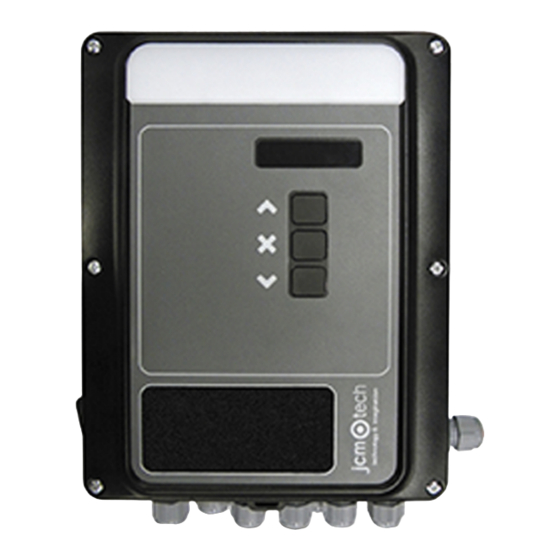
Introduction General description Single-phase control panel with 2 motors with soft stop for residential and community use. Control by JCM, Elektromaten or Kostal digital absolute encoder (motor 1 only) or by limit switches. Detailed description 1- RECEIVER 12- 12/24VDC / TEST OUTPUT Motion STICK receiver connector 2 outputs 12Vac/dc range: 11,4V to 12,6V... -
Page 6: Indication Leds
Indication LEDs LED ON GREEN Led indicates control panel power supply LED PROG Led indicates programming activation LEDs INPUTS Leds indicate input activation LEDs OUTPUTS GREEN Leds indicate output activation Leds indicate activation of the motor movement button and direction LEDs MOTOR YELLOW If Leds flash, they indicate slow speed... -
Page 7: Installation
Installation Install the control panel vertically on the wall at a height of 1.5m and following the assembly instructions. Connections POWER SUPPLY AND MOTOR CONNECTIONS OUTPUTS INPUTS jcmtechnologies... - Page 8 PHOTOCELL CONNECTION WITH AUTOTEST ABSOLUTE ENCODER CONNECTION jcmtechnologies...
-
Page 9: Configuration
Configuration Options selector By default all selectors leave the factory set to OFF. OPTIONS SELECTOR Do not closes automatically 1- AUTOCLOSE Closes automatically Slow speed available at the end of Normal speed in all the manoeuvre 2- SLOW SPEED the manoeuvre Enables the operation by end limit Enables the operation by ABS 3- ABSENCODER/LIMITSW... -
Page 10: Starting
Starting up Door Positioning 2PRESS MOTOR2 CLOSE TO 4PRESS MOTOR1 CLOSE TO 1PRESS PROG BUTTON CLOSE IN DM 3DOOR 2 CLOSES CLOSE IN DM 5DOOR 1 CLOSES 6PRESS PROG BUTTON 7LED TURNS OFF 8END DOOR POSITIONING Considerations: In step 2, if MOTOR2 CLOSE is pressed and the door opens, reverse the motor 2 wires, and return to step 1. In step 4, if MOTOR1 CLOSE is pressed and the door opens, reverse the motor 1 wires, and return to step 1. -
Page 11: Programming 1
Programming Maneuver programming with two motors with slow speed To program the door maneuver is necessary to use the PROG button to start programming and the START button to per- form each step in the sequence. 3PRESS WHITE PROG 4PRESS BLACK START 1DOORS CLOSED 2SET OPTIONS 2&6 AT ON UNTIL LED ON... -
Page 12: Maneuver Programming With Two Motors Without Slow Speed
* ¤22DOOR 2 CLOSES SLOW * 24DOOR 1 CLOSES SLOW * ¤21PRESS START BUTTON SPEED * 23PRESS START BUTTON SPEED ¤26DOOR 2 STOPS ¤25PRESS START BUTTON (CLOSED) 27PRESS START BUTTON 28DOOR 1 STOPS (CLOSED) 29LED TURNS OFF 30END PROGRAMMING Maneuver programming with two motors without slow speed In step 2, set only the 6 option at ON. -
Page 13: Troubleshooting 1
Troubleshooting Indicator light for possible faults, LED ERROR ERROR LED ERROR INDICATION SOLUTION Consult the technical ser- 10 slow flashes Er 02 INTERNAL ERROR Internal error vice 2 quick flashes Program a maneuver Programming time max- 10 slow flashes Er 09 PROG TIME MAX below the maximum imum... - Page 14 Program the control panel Control panel pro- again without using RBAND NOT grammed with RBAND RBAND or connect the 3 slow flashes Er 30 FOUND connected and now it is RBAND that was con- 10 quick flashes not connected nected to the control panel previously Control panel not pro- Connect the RBAND card...
-
Page 15: Notes 1
Notes jcmtechnologies... -
Page 16: Technical Data 1
Regulatory Data EU Declaration of conformity JCM TECHNOLOGIES, S.A. declares that the product M42 complies with the relevant fundamental requirements of the Machine Directive 2006/42/EC as well as with the Directives 2014/30/EU on electromagnetic compatibility and 2014/35/EU regarding low voltage whenever its usage is foreseen; and with the 2011/65/EU RoHS Directive.
Need help?
Do you have a question about the M42 and is the answer not in the manual?
Questions and answers