Advertisement
Quick Links
Advertisement

Related Manuals for True WING KITCHEN


Summary of Contents for True WING KITCHEN
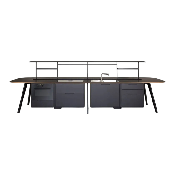
- Page 1 WING KITCHEN assembly instructions istruzioni montaggio instructions de montage...
- Page 2 Components Componenti | Éléments...
- Page 5 top access A top access B...
- Page 6 M4x10mm M6x14mm M6x16mm M8x16mm M10x55mm M5x10mm M6x16mm M6x20mm M10x70mm M4x30mm...
- Page 7 Step Step Secure the 2 legs B to the 2 beams A through the 8 M10x55mm screws. Secure every M10x55mm screw with a washer D and a blind nut E. Fissare le 2 gambe B alle 2 travi A tramite le 8 viti M10x55mm. Fissare ogni vite M10x55mm con una rondella D e un dado cieco E. Fixez les 2 pieds B aux 2 poutres A avec les 8 vis M10x55mm.
- Page 8 Step Step Connect the two previously installed structures to leg C through the 4 M10x70 mm screws. Secure each screw with two washers D and a blind nut F. Unire le due strutture precedentemente installate alla gamba C tramite le 4 viti M10x70mm. Fissare ciascuna vite con due rondelle D ed un dado F.
- Page 9 Step Step Adjust the feet of each leg up to the preferred height in order to guarantee stability on the floor. Regolare i piedini di ciascuna gamba fino al’altezza desiderata che garantisca stabilità sul piano. Réglez les pieds de chaque pied jusqu'à la hauteur souhaitée pour garantir la stabilité sur le sol.
- Page 10 Step Step Secure, from above, every element G to every beam A, each with the 4 M6x20 mm screws. Fissare, da sopra, ogni elemento G a ogni trave A, ciascuna con le 4 viti M6x20mm. Fixez, en haut, chaque élément G à chaque poutre A, avec les 4 vis M6x20 mm chacune. M6x20mm...
- Page 11 Step Step Adjust the feet of elements G up to the preferred height to guarantee stability on the floor. Cover the feet securing elements H to elements G. Regolare i piedini degli elementi G fino al’altezza desiderata che garantisca stabilità sul piano. Coprire i piedini fissando gli elementi H agli elementi G.
- Page 12 Step Step Put the top J on the right beam and secure it with 4 M6x16mm screws, to ensure stability. Verify that on top J there are 4 cams and 4 plates Appoggiare il piano J sulla trave destra e fissarlo con 4 viti M6x16mm, per garantirgli un’iniziale stabilità. Verificare che sul piano J siano presenti 4 eccentrici e 4 lamelle.
- Page 13 Step Step Put the top K on the left beam and slot it with the top J through the cracks for the cams and the plates. Appoggiare il piano K sulla trave sinistra e incastrarlo con il piano J tramite le fessure per gli eccentrici e le lamelle. Appuyez l’étage K à...
- Page 14 Step Step To ensure the stability of the two tops J and K, screw the 4 M8 set screws into the four holes present on the inside of top K. Per garantire stabilità ai due piani J e K, avvitare con un cacciavite i 4 grani M8 nei quattro fori presenti all’interno del piano K. Pour garantir la stabilité...
- Page 15 Step Secure the 2 tops to the beams through the 36 M6x16mm screws. Fissare i due piani alle travi tramite le 36 viti M6x16mm. Fixez les 2 étages aux poutres avec les 36 vis M6x16mm. M6x16mm...
- Page 16 Step Initially secure the 10 tie-rods L into the 10 socket wrenches present on the top and then slot it in the first box M. Fissare dapprima i 10 tiranti L nelle 10 bussole presenti sul piano e successivamente incastrarvici la prima scatola M. Fixez d’abord les 10 tirants L dans les 10 douilles placées sur l’étage et puis piègez la première boîte M.
- Page 17 Step To keep the box M secured to the top, insert into the internal 10 holes of the box the ten M8 set screws. Per tenere fissata la scatola M al piano, inserire nei 10 fori interni della scatola i dieci grani M8. Pour maintenir la boîte M fixée à...
- Page 18 Step Repeat the same procedure of step 10 with the box N and the 10 tie-rods L. Ripetere lo stesso procedimento dello step 10 con la scatola N e i 10 tiranti L. Répétez la même procédure de l’étape 10 avec la boîte N et les 10 tirants L.
- Page 19 Step Repeat the same procedure of step 11 with the 10 M8 set screws. Ripetere lo stesso procedimento dello step 11 con i 10 grani M8. Répétez la même procédure de l’étape 11 avec les 10 grains M8.
- Page 20 Step Secure, from underneath, with element Q, the boxes M and N and the element G through the 8 M6x16mm and the 3 M8x16mm screws. Fissare, da sotto, con l’elemento Q, le scatole M ed N e l’elemento G tramite le 8 viti M6x16mm e le 3 viti M8x16mm. Fixez, par le bas, avec l’élément Q, les boîtes M et N et l’élément G avec les 8 vis M6x16mm et les 3 vis M8x16mm.
- Page 21 Step Repeat the same procedure of step 10 with the box O and the 10 tie-rods L. Ripetere lo stesso procedimento dello step 10 con la scatola O e i 10 tiranti L. Répétez la même procédure de l’étape 10 avec la boîte O et les 10 tirants L.
- Page 22 Step Repeat the same procedure of step 11 with the 10 M8 set screws. Ripetere lo stesso procedimento dello step 11 con i 10 grani M8. Répétez la même procédure de l’étape 11 avec les 10 grains M8.
- Page 23 Step Repeat the same procedure of step 10 with the box P and the 10 tie-rods L. Ripetere lo stesso procedimento dello step 10 con la scatola P e i 10 tiranti L. Répétez la même procédure de l’étape 10 avec la boîte P et les 10 tirants L.
- Page 24 Step Repeat the same procedure of step 11 with the 10 M8 set screws. Ripetere lo stesso procedimento dello step 11 con i 10 grani M8. Répétez la même procédure de l’étape 11 avec les 10 grains M8.
- Page 25 Step Secure, from underneath, with element Q, the boxes O and P and the element G through the 8 M6x16mm and the 3 M8x16mm screws. Fissare, da sotto, con l’elemento Q, le scatole O ed P e l’elemento G tramite le 8 viti M6x16mm e le 3 viti M8x16mm. Fixez, par le bas, avec l’élément Q, les boîtes O et P et l’élément G avec les 8 vis M6x16mm et les 3 vis M8x16mm.
- Page 26 Step Rely on the reference manual for the mounting of element T. Take care to let the wire slide on the inside of beam A up to the tubular support G. Wait for an electrician for ist proper functioning. Affidarsi al manuale di riferimento per il montaggio dell’elemento T. Avere cura di far scorrere il filo all’interno della trave A fino al sostegno tubolare G.
- Page 27 Step Insert the drawer S1 into the rails and push it until it closes. To remove the drawer completely from the rails, push on the appropriate lever, as shown in detail, and pull the drawer to themselves. Inserire il cassetto S1 nelle guide e spingerlo fino a chiusura. Per rimuovere completamente il cassetto dalle guide, premere sull’apposita leva, come indicato nel dettaglio, e tirare il cassetto fino a sè.
- Page 28 Step Repeat the same procedure for the others available drawers S, placing them into the positions shown on the scheme. Ripetere lo stesso procedimento per tutti gli altri cassetti S a disposizione, collocandoli nelle posizioni illustrate nello schema. Répétez la meme procedure pour les autres tiroirs S à disposition, en les plaçant dans les positions illustrées dans le plan.
- Page 29 Step Before inserting the oven, let the cable slide into the proper slot of the box M along the beam up to the tubular support G. Wait for an electrician to connect to a power outlet. Prima di inserire il forno, far scorrere il cavo nell’apposita fessura della scatola M lungo la trave fino al sostegno tubolare G. Attendere un elettricista per collegare a una presa corrente.
- Page 30 Step Open the door of the oven and secure the 4 M4x30mm chipboard screws to the side edges of the box M. Aprire la porta del forno e fissare ai bordi laterali della scatola M le 4 viti truciolari M4x30mm. Ouvrez la porte du four et fixez aux bords latéraux de la boîte M les 4 vis de bois aggloméré...
- Page 31 Step Insert the drawer for the vacuum into the box M securing it to the side edges with 4 M4x30mm chipboard screws. Inserire il cassetto del sottovuoto nella scatola M fissandolo ai bordi laterali con 4 viti truciolari M4x30mm. Insérez le tiroir pour le sous vide dans la boîte M en le fixant aux bords latéraux avec 4 de vis de bois aggloméré M4x30mm. M4x30mm The opening of the vacuum drawer is regulated by a pressure mechanism which is operated putting the...
- Page 32 Step Before securing the induction hob, put the silicone along the edges of the cavity of the box, as shown in figure. Prima di fissare il piano a induzione, passare il silicone lungo i bordi della cavità della scatola, come indicato in figura. Avant de monter la plaque à...
- Page 33 Step Before securing the induction hob, let the wire unroll, making it go through the slot at the top left of the box and through the slots of the beam and the tubular support. Wait for an electrician to connect to a power outlet. Prima di procedere al fissaggio del piano a induzione, far srotolare il cavo corrente, facendolo attraversare nella fessura in alto a sinistra della scatola e per le fessure della trave e del sostegno tubolare.
- Page 34 Step Rely on a hydraulic for the assembly of the sink and its components. In the end, insert the element R4 into the drawer. Si raccomanda di affidarsi a un idraulico per il montaggio del lavello e delle sue componenti. Al termine, inserire l’elemento R4 nel cassetto. Faire appel à...
- Page 35 Step Insert the four tube holders V into the cavities of each top and secure each with the two nuts E. Inserire i quattro portatubi V nelle due cavità di ogni piano e fissare ciascuno con i due dadi E. Inséréz les quatre porte-tuyaux dans les cavités de chaque étage et fixez chacun avec les deux écrous E.
- Page 36 Step Insert the trays W inside the slots present on the tops. Don’t secure with the screws. Inserire le vaschette W all’interno delle fessure presenti sui piani. Non fissare con le viti. Inséréz les barquettes W à l’intériéur des fentes placées sur les étages. Ne fixer pas avec les vis.
- Page 37 Step Place the slabs Y1 and Y2 correcty as detailed, before these are secured to the trays through some magnets. Posizionare correttamente le piastre Y1 e Y2 come indicato nei dettagli, prima che queste vengano fissate alle vaschette tramite le calamite. Positionnez correctement les plaques Y1 et Y2 comme indiqué...
- Page 38 Step Insert the tubes Z1, Z2 and Z3 with the elements Z4 and the shelves Z5 as shown in the scheme. Inserire i tubi Z1, Z2 e Z3 con gli elementi Z4 e le mensole Z5 come illustrato nello schema. Inséréz les tuyaux Z1, Z2 et Z3 avec les éléments Z4 et les étagères Z5 comme indiqué...
- Page 39 Step Secure the elements of the previous step through the 8 M4x10mm screws. Fissare gli elementi dello step precedenti tramite le 8 viti M4x10mm. Fixez les élémets de l’étape précédent avec les 8 vis M4x10mm. M4x10mm...
- Page 40 Step Insert the previously installed structure into the 4 tube holders securing them with 2 M6 set screws each. Secure the tube Z3 through the 2 screws and lastly hide the fixing with elements Y3 and Y4. Inserire la struttura precedentemete installata nei 4 porta tubi fissandoli con 2 grani M6 ciascuno. Fissare il tubo Z3 con le 2 viti e infine nascondere il fissaggio con gli elementi Y3e Y4.
- Page 41 Step Turn the 2 lampshades Z6 and frame for each, from the aluminum side, the 2 LED lamps making sure that the wire comes out into the cavities. Capovolgere i 2 paralumi Z6 e incastrarvi per ciascuno, dal lato di alluminio, le 2 lampade LED avendo cura che il filo fuoriesca nelle cavità. Retournez les 2 abat-jour Z6 et piégez pour chaque , du côté...
- Page 42 Step Before mounting the 2 lampshades, lift the tray W and let the 2 LED lamps wires of each lampshade, slide inside the tube Z3 along all the beam A up to the tubular support G Prima di montare i due paralumi, alzare la vaschetta W e far scorrere i due fili delle lampade LED di ciascun paralume all’interno del tubo Z3 percorrendo tutta la trave A fino al sostegno tubolare G.
- Page 43 Step Choose the position where to put elements U. (detail 1) Insert the wires into the feeder (detail 2) and unroll the wire into the tubular support G. (detail 3). For the starting and the turning off of the 2 LED lamps press on the appropriate button. (detail 4) Wait for an electrician before connecting to a power outlet.
- Page 44 Step Slot each lampshade Z6 into the 2 tubes Z1 et Z2 present on the top and secure it to the tube Z3 through the 4 M6x14mm screws. Secure the two lampshades to the tubes Z1 et Z2 through the 4 M8x16mm screws. Incastrare ciascun paralume Z6, nei due tubi Z1 E Z2 presenti sul piano e fissarlo al tubo Z3 con le 4 viti M6x14mm.
- Page 45 Step Secure the doors I , with the flat face outwards, to the elements G through the 12 M5x10mm screws. Fissare le porte I, con la faccia piana rivolta verso l’esterno, agli elementi G mediante le 12 viti M5x10mm. Fixez les portes I avec la face plate tournée vers l'extérieur aux éléments G avec les 12 vis M5x10mm. M5x10mm...
- Page 46 Step Secure the elements X1 and X2 into the beams A through the 16 M5x10mm screws. Fissare gli elementi X1 e X2 nelle travi A mediante le viti 16 M5x10mm. Fixez les éléments X1 et X2 dans les poutres A avec les 16 vis M5x10mm. M5x10mm...
- Page 47 Step Insert the 4 top accesses into the trays. Inserire i 4 top acces nelle vaschette. Inserez les 4 top accesses dans les barquettes. top access A top access B top access B top access A...
- Page 48 True Design s.r.l. Via Leonardo Da Vinci 2 - 35040 Sant’Elena (PD) Italy Tel. +39 0429 692483 - info@truedesign.it - www.truedesign.it...
Need help?
Do you have a question about the WING KITCHEN and is the answer not in the manual?
Questions and answers