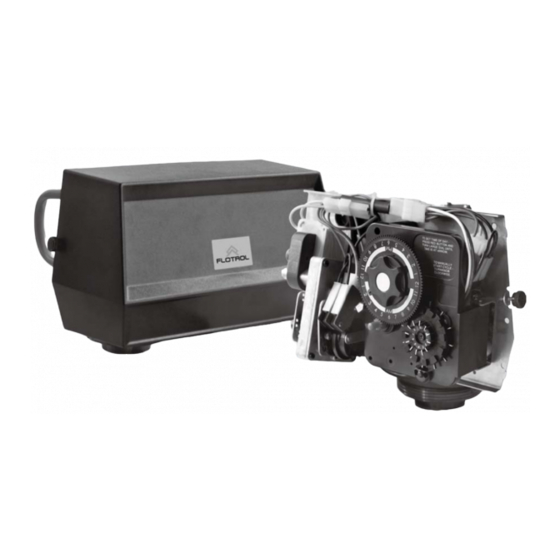
Summary of Contents for Flotrol F40
- Page 1 MODEL F40 Service Manual IMPORTANT: Fill in pertinent information on page 2 for future reference.
-
Page 3: Job Specification Sheet
MODEL F40 Job Specification Sheet * JOB NO. * MODEL NO. * WATER TEST * CAPACITY PER UNIT * MINERAL TANK SIZE DIA. HEIGHT * BRINE TANK SIZE & SALT SETTING PER REGENERATION: * 2850 CONTROL VALVE SPECIFICATIONS 1 Type of Timer (see pages 10,11, and 12) -
Page 4: General Commercial Pre-Installation Check List
MODEL F40 General Commercial Pre-Installation Check List WATER PRESSURE: A minimum of 25 pounds of water pressure is required for regeneration valve to operate effectively. ELECTRICAL FACILITlES: A continuous 115 volt, 60 Hertz current supply is required. Make certain the current supply is always hot and cannot be turned off with another switch. - Page 5 MODEL F40 Assembly Drawings and Part Numbers F40 Control Valve Assembly FILTER PARTS RWB PISTON ASSEMBLY BLOCK-A BLOCK-B NRWB PISTON ASSEMBLY BLOCK-C BLOCK-B Page 4...
- Page 7 MODEL F40 Control Drive Assembly (For F30 & F40 Mechanical Clock) FOR SM 13-2 13-1 14-1 14-2 Page 6...
- Page 8 MODEL F30 Control Drive Assembly (For F30 & F40 Mechanical ) Item No. Quantity Part No. Description 053-00014-00 Motor1 Assembly 220V 051-00084-00 Brine Valve Cam 068-00001-00 Roll Pin- Drive Assembly 099-00175-00 Drive Cam Assembly 052-00049-00 Insulator -Drive Assembly 043-00000-00 Switch 1 066-00000-00 Screw,tcp,NO.4-40x1.125,b,Zn,1022...
- Page 9 MODEL F40 Timer Assembly (For Mechanical Clock) Page 8...
- Page 10 MODEL F40 Timer Assembly (For Mechanical Clock) Item No. Quantity Part No. Description 051-00078-00 Timer Housing 069-00180-00 Decal- Instructions 051-00074-00 Cycle Actuator Arm 099-00177-00 24 Hour Gear Assembly 051-00089-00 Knob 066-00002-00 Screw,tchw,NO.6-20x1/2,b,black,Zn,1022 069-00179-00 Button Decal 099-00176-00 Skipper Wheel Assembly 078-00008-00...
- Page 11 MODEL 3200 & 3210 TIMER SERIES Regeneration Cycle program Setting Procedure Even though it takes three hours for this center knob to Typical Programming Procedure complete one revolution, the regeneration cycle of your unit might be set for only one half of this time. Calculate the gallon capacity of the system, subtract the necessary reserve requirement and set the gallons required by Iifting the gallon dial and rotating it so...
-
Page 12: Timer Setting Procedure
MODEL 3200 & 3210 TIMER SERIES Timer Setting Procedure Service How To Set Days On Which Water 24 HR. Gear Position Manual Conditioner Is To Regenerate: Indicator Regeneration Rotate the skipper wheel until the number “1” is at the red Knob pointer. - Page 13 MODEL 3200 & 3210 TIMER SERIES Regeneration Cycle program Setting Procedure How To Set The Regeneration Cycle Pro- How To Change The Length Of Rapid Rinse: The second group of pins on the program wheel deter- gram: The regeneration cycle program on your water conditioner mines the Iength of time that your water conditioner will has been factory preset, however, portions of the cycle or rapid rinse.
- Page 14 MODEL F40 Assembly Drawings and Part Numbers Medium Brining System Assembly a.Brine Tube(NRWB) b.Brine Tube(RWB) BLOCK-A BLOCK-C Fittings for medium (1" to 1/2") brining system BLOCK-B Fittings for 1/2" BV Page 13...
- Page 16 MODEL F40 Assembly Drawings and Part Numbers 1.5" Flow Meter Assembly Mechanical Meter Cover Assembly Electronic Meter Cover Assembly Page 15...
- Page 17 MODEL F40 Assembly Drawings and Part Numbers 1.5" Flow Meter Assembly Parts List Item No. Quantity Part No. Description 061-00002-00 Meter Cable Assembly(16.5”) 066-00048-00 Screw,ch,M5x15mm,A2-70 099-00195-00 Meter Cover Assembly 066-00012-00 Screw,tchw,NO.8-18x3/8,Zn,1022 047-00019-00 Meter Cable Assembly(35”) 047-00013-00 Meter Cable Assembly(99.5”) 099-00881-00...
- Page 18 MODEL F40 Dimensional Drawing 2)F40 Valve " " 320mm (12.6") 181mm (7.1") 4" UN NRWB " " 320mm (12.6") 194mm (7.6") 4" UN Page 17...
- Page 19 100-00003-00 Fittings for medium (1” to ½” brining 100-00008-00 Piston Kits-RWB system 100-00027-00 Fittings for 1/2” BV Seals & Spacers Injector 100-00050-00 F40 Spacers & Seals 100-00021-00 #5 Injector Assembly 100-00026-00 #6 Injector Assembly Meter(1.5" Electronic Flow Meter) Meter(1.5" Extended Mechanical Flow Meter) 100-00028-00 35" Cable 100-00006-00 100-00005-00 99.5"...
- Page 20 MODEL F40 Service Instructions PROBLEM CAUSE CORRECTION Softener fails to regenerate. A. Electrical service to unit has been interrupted. A. Assure permanent electrical service (check fuse, plug, pull chain or switch). B. Timer is defective. B. Replace timer. C. Power failure.
-
Page 21: General Service Hints For Meter Control
MODEL F40 Service Instructions PROBLEM CAUSE CORRECTION Softener fails to draw brine. Drain Iine fIow controI is pIugged. Clean drain Iine flow control. Clean injector. Injector is plugged. Clean screen. Injector screen plugged. lncrease Iine pressure to 20 P.S.I. Line pressure is too low. - Page 22 MODEL F40 Note Page 21...
- Page 23 MODEL F40 Note Page 22...
- Page 24 AAHK076-00004-00V1.0...


Need help?
Do you have a question about the F40 and is the answer not in the manual?
Questions and answers