Table of Contents
Advertisement
Quick Links
FILE NO. 210-200805GR
SERVICE MANUAL
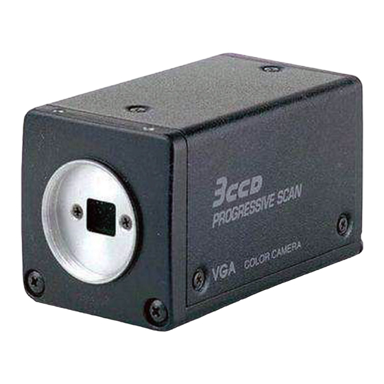
CCD CAMERA
IK-TF5P
IK-TF5P
The above model is classified as a green product (*1), as indicated by the letter marking (G)
after model name. This Service Manual describes replacement parts for the green product.
When repairing this green product, use the part(s) described in this manual and lead-free
solder (*2).
For (*1) and (*2), see the next page.
Published in Japan, Mar. 2009 (TD)
TOSHIBA CORPORATION 2009
Advertisement
Table of Contents

Related Manuals for Toshiba IK-TF5P


Summary of Contents for Toshiba IK-TF5P
- Page 1 This Service Manual describes replacement parts for the green product. When repairing this green product, use the part(s) described in this manual and lead-free solder (*2). For (*1) and (*2), see the next page. Published in Japan, Mar. 2009 (TD) TOSHIBA CORPORATION 2009...
- Page 2 WARNING This product is manufactured using lead free solder. DO NOT USE LEAD BASED SOLDER TO REPAIR THIS PRODUCT !
- Page 3 SAFETY NOTICE SAFETY PRECAUTIONS LEAKAGE CURRENT CHECK The AC line cord of power supply connect to terminal. Measure the AC voltage across the 1500W resistor. And plug the AC line cord of power supply into a 120V The test must be conducted with the AC switch on and AC outlet.
-
Page 4: Table Of Contents
CONTENTS SECTION 1 GENERAL DESCRIPTION 1. CAUTIONS ON USE AND INSTALLATION ......1-2 7. MODE SETTING BY ON SCREEN DISPLAY ...... 1-5 2. COMPONENTS ..............1-2 8. INPUT OUTPUT SIGNAL SPECIFICATIONS ....1-17 3. NAMES AND FUNCTIONS ..........1-3 9. CCD OUTPUT WAVEFORM TIMING CHART ....1-17 4. - Page 5 SECTION 1 GENERAL DESCRIPTION IK-TF5P...
- Page 6 IK-TF5P IK-TF5P...
- Page 7 IK-TF5P...
- Page 8 IK-TF5P IK-TF5P...
- Page 9 IK-TF5P...
- Page 10 IK-TF5P IK-TF5P...
- Page 11 IK-TF5P...
- Page 12 IK-TF5P IK-TF5P...
- Page 13 IK-TF5P...
- Page 14 1-10 IK-TF5P IK-TF5P...
- Page 15 1-11 IK-TF5P...
- Page 16 1-12 IK-TF5P IK-TF5P...
- Page 17 1-13 IK-TF5P...
- Page 18 1-14 IK-TF5P IK-TF5P...
- Page 19 1-15 IK-TF5P...
- Page 20 1-16 IK-TF5P IK-TF5P...
- Page 21 1-17 IK-TF5P...
- Page 22 1-18 IK-TF5P IK-TF5P...
-
Page 23: Electrical Adjustment Procedures
· PC (with a frame grabber installed) · Lens · Plastic chip screwdriver · Gray scale chart, color bar chart · Lights (TOSHIBA photo reflector lamp 500W x 2, or a halogen lamp 500W x 2) · PoCL Cable (EXC-CL05S) IK-TF5P... - Page 24 So set the light equipments to give an even illumination. CA22 TC02 Note: Perform the adjustments in a dustless location to prevent inside of the camera unit from dirty Fig.3 Process PC board (external side) IK-TF5P...
-
Page 25: Total Adjustments
1. Set the lens iris to close. 2. Press the DATA buttons. 1-2-5. ABB Adjustment 3. The automatic black balance adjustment is performed automatically and “ABB OK” is displayed on the screen. 1-2-6. Screen Display Confirmation 1-2-7. White Pixel Masking IK-TF5P... - Page 26 R/G value on the screen obtains 100 data so that the R/G value on the screen obtains 100 ± 1. ± 1. 1100 ± 40mV 1100 ± 40mV (TC02) (TC02) Adjust the R/G value to 100 Adjust the R/G value to 100 IK-TF5P...
- Page 27 2. After more than 15 minutes continuity, set the lens iris to close and keep pressing the DATA DOWN button for a long times at approx. 7 seconds. 3. The automatic white pixel masking is performed automatically and “PIX OK” is displayed on the screen. IK-TF5P...
-
Page 28: Exploded Views
The mounting position of replacement is to be identical with originals. The substitute replacement parts which do not have the same safety characteristics are specified in the parts list may create shock, fire or other hazards. 1. EXPLODED VIEWS 1-1. Packing Assembly IK-TF5P... -
Page 29: Camera Head Assembly
1-2. Camera Head Assembly A104 A104A A104A S001 A104A UC05 PM06A A109D UC04 A103A W011 A103 UC02 A001S H001 A109B PM06 A109C UC03A A106 A107 UC01 A001A UC03 A101 A102 A108 A105A A101A IK-TF5P... - Page 30 CC41 76105101 Cap,Chip,Ceramic 100pF J 50V QC16 23085124 IC TC7SH32FU CC42 76105101 Cap,Chip,Ceramic 100pF J 50V QC32 75012999 IC NJM2872BF24 CC43 76092730 Cap,Chip,Ceramic 0.1μF K 16V -RESISTORS- CC44 76105101 Cap,Chip,Ceramic 100pF J 50V RA01 76019405 Res,Chip 15kW D 1/16W IK-TF5P...
- Page 31 10pF J 50V RC90 75011954 Res,Chip 10W D 1/16W CH43 76109103 Cap,Chip,Ceramic 0.01μF K 50V RC93 75005003 Res,Chip 22W D 1/16W CH44 76105100 Cap,Chip,Ceramic 10pF J 50V RC94 75011954 Res,Chip 10W D 1/16W CH45 76088103 Cap,Chip,Tantalum 100μF M 6.3V IK-TF5P...
- Page 32 23085125 IC TC7SZ00FU RH73 75006062 Res,Chip 15kW D 1/16W QH30 23085153 IC SN74AHCT1G00DCKR RH76 75011947 Res,Chip 4300W D 1/16W QH31 23085153 IC SN74AHCT1G00DCKR RH77 75011954 Res,Chip 10W D 1/16W -TRANSISTORS- RH81 75011956 Res,Chip 100W D 1/16W QH25 23205477 Transistor,Chip 2SA1774Q IK-TF5P...
- Page 33 0.1μF K 16V CM59 76109103 Cap,Chip,Ceramic 0.01μF K 50V CB03 76092730 Cap,Chip,Ceramic 0.1μF K 16V CM60 76109103 Cap,Chip,Ceramic 0.01μF K 50V CB05 76092730 Cap,Chip,Ceramic 0.1μF K 16V CM61 76109103 Cap,Chip,Ceramic 0.01μF K 50V CB06 76109473 Cap,Chip,Ceramic 0.047μF K 25V IK-TF5P...
- Page 34 200W D 1/16W RB07 75013014 Res,Chip 130W D 1/16W RR11 75011956 Res,Chip 100W D 1/16W RB08 75011946 Res,Chip 3000W D 1/16W RR12 75011946 Res,Chip 3000W D 1/16W RB09 75011941 Res,Chip 200W D 1/16W RR13 75005003 Res,Chip 22W D 1/16W IK-TF5P...
- Page 35 76014104 Cap,Chip,Ceramic 0.1μF K 6.3V CZ54 76014104 Cap,Chip,Ceramic 0.1μF K 6.3V CZ56 76092463 Cap,Chip,Ceramic 0.22μF K 16V CZ58 76088103 Cap,Chip,Tantalum 100μF M 6.3V CZ60 76088103 Cap,Chip,Tantalum 100μF M 6.3V -INTEGRATED CIRCUITS- QX51 70129349 IC CXA1439M QX52 23085125 IC TC7SZ00FU IK-TF5P...
- Page 36 23528404 Filter pack A107 75010078 Optical filter A108 70869181 C Mount Cap A109B 75013026 Washer A109C 75013027 Nut A109D 23717245 Screw PM06A 23727012 Screw 12600-S-12 UC03A 23717245 Screw A701 70917900 Carton A707 75007402 Rabel Y110 75013029 Instruction manual IK-TF5P IK-TF5P...
-
Page 37: Pc Boards
SECTION 4 PC BOARDS AND SCHEMATIC DIAGRAMS 1. PC BOARDS 1-1. Sub PC Board Top Side Bottom Side IK-TF5P... -
Page 38: Process Pc Board
1-2. Process PC Board Top Side Bottom Side IK-TF5P... -
Page 39: Tg Pc Board
1-3. TG PC Board Top Side Bottom Side IK-TF5P... -
Page 40: Mother Pc Board
1-4. Mother PC Board Top Side IK-TF5P... - Page 41 Bottom Side IK-TF5P...
-
Page 42: Rear Pc Board
1-5. Rear PC Board Top Side Bottom Side IK-TF5P... -
Page 43: Block Diagrams
AMP, CLIP GAIN AMP from HEAD QG03 QG04 REF P,. CLAMP QG03 QG05 CLAMP PBLB QB02 ZB03,ZB04 QB11,QB12,QB13,QB14 VARIABLE PA_B HE B AMP, CLIP GAIN AMP QB03 QB04 REF P,. CLAMP QG03 QG05 CLAMP QB09 REF PLUSE PW02 To MOTHER IK-TF5P... -
Page 44: Process(1/2), (2/2) Block Diagram
QA04 QA05 RESET QC16 EEPROM KEYOUT0 KEYOUT1 From MC K PC01 KEYIN0 PROCESS 1/2 KEYIN1 To MOTHER L DDSP SDODSP KEYIN2 RST2 CL A 〜 D GMN I E SEL0 〜 1 BUND 0 〜 15 CHARA FUCHI 4-10 IK-TF5P... - Page 45 QH06 -7.5V XSHP QH08 QH09 -7.5VH QH07 QH29 QH10 QH01 QH23 XV3,XSG, QH30 XV2,XV1 WPBL V driver QH31 QH51〜 QH02 QH54 Configuration ΦVsub driver QH14 RST3 QH16 INDEX,CBLK X'tal TRIG SHADING ZH04 D-SHAD SHAD CORRECTION QH18,QH19 QH23 4-11 4-12 IK-TF5P...
- Page 46 WB G WB B X0+/- X1+/- WPBL X2+/- X3+/- BD0-7 Xclk+/- FVAL LVAL QM04 12V-3 QM05 SW-REG 1.5V +1.2V S-REG QM13 PCLK CC1+/- 3.6V CC2+/- QM10 SerTC+/- LVDS +3.1V TRIG RECEIVER PART +3.1V QM11 SerTFG+/- LVDS DRIVER 4-13 4-14 IK-TF5P...
- Page 47 3. CIRCUIT DIAGRAMS 3-1. Overall Wiring Diagram 4-15 4-16 IK-TF5P...
-
Page 48: Sub Circuit Diagram
3-2. Sub Circuit Diagram 4-17 4-18 IK-TF5P... -
Page 49: Process Circuit Diagram
3-3. Process Circuit Diagram 3-3-1. Process Circuit Diagram-1 4-19 4-20 IK-TF5P... - Page 50 3-3. Process Circuit Diagram 3-3-2. Process Circuit Diagram-2 4-21 4-22 IK-TF5P...
-
Page 51: Tg Circuit Diagram
3-4. TG Circuit Diagram 4-23 4-24 IK-TF5P... -
Page 52: Mother Circuit Diagram
3-5. Mother Circuit Diagram 3-5-1. Mother Circuit Diagram-1 4-25 4-26 IK-TF5P... - Page 53 3-5. Mother Circuit Diagram 3-5-2. Mother Circuit Diagram-2 4-27 4-28 IK-TF5P...
-
Page 54: Head Circuit Diagram
3-6. Head Circuit Diagram 4-29 4-30 IK-TF5P... - Page 55 Partial scanning control CC2 (LVDS input) signal input Interface Serial data interface : Ser TC (RXD), Ser TFG (TXD) The designs and specifications are subject to change without notice. If any change occurs, we will revise the manual, etc. IK-TF5P...
Need help?
Do you have a question about the IK-TF5P and is the answer not in the manual?
Questions and answers