Table of Contents
Advertisement
Quick Links
Advertisement
Table of Contents

Related Manuals for JETI model MAX BEC


Summary of Contents for JETI model MAX BEC
- Page 1 MAX BEC / SBEC MAX BEC / SBEC ® MAX BEC / SBEC MAX BEC / SBEC User manual...
-
Page 2: Table Of Contents
2.4.3 Switch - Magnetic switch ..........11 EN 2.4.4 Switch - RC switch ............11 EN 2.4.5 Connection of MAX BEC 2D Plus telemetry to the Duplex receiver .............. 12 EN 2.4.6 Parameters MAX BEC 2D plus ........13 EN 3. - Page 3 MAX BEC / SBEC MAX BEC / SBEC 3.1.2 Wiring ................14 EN 3.1.3 Switch ................14 EN 3.1.4 Heat protection ............14 EN 3.1.5 Parameters SBEC ............15 EN 3.2 SBEC 30D ................. 16 EN 3.2.1 Output voltage setting ..........16 EN 3.2.2 Wiring ................
-
Page 4: Introduction
MAX BEC / SBEC Introduction English The MAX BEC / SBEC voltage regulator is designed to power the on-board system in the model (receiver and servo power supply), which uses LiXX cells to power it. The regulator ensures that the power supply... -
Page 5: Linear Voltage Regulator
MAX BEC / SBEC MAX BEC / SBEC Linear voltage regulator 2.1 Single BEC 2.1 Single BEC Single BEC is a linear regulator to provide power for a standard servo with a maximum input voltage of 6V. The Single BEC can also be used to provide power for the control units of helicopters or multicopters. -
Page 6: Parameters Single Bec
2.2 MAX BEC 2.2 MAX BEC MAX BEC can be supplied either by NiXX or LiXX cells, recommended is 2 LiXX cells or 5-6 NiXX cells. Input voltage is indicated by four LEDs. If the input voltage is above 7.0 V, all three green LEDs are ON. -
Page 7: Parameters Max Bec
5.0 V, 5.4 V, 5.7 V and 6.0 V. The MAX BEC 2 supply can consist of LiXX or NiXX cells. For this purpose we recommend application of 2 LiXX cells or 5-6 NiXX cells. -
Page 8: Wiring
2.3.2 Wiring The supply batteries should be connected by cables of a cross section of at least 1.5 mm to the terminals of the MAX BEC 2 marked ACCU 1 and 2. The MAX BEC 2 regulator allows connection of two supply batteries. - Page 9 MAX BEC / SBEC MAX BEC / SBEC output voltage selection ACCU 2 ACCU 2 ACCU 1 ACCU 1 9 EN...
-
Page 10: Max Bec 2D Plus
2.4.2 Wiring The supply batteries should be connected by cables of a cross section of at least 1.5 mm to the terminals of the MAX BEC 2D Plus marked ACCU A and B. The MAX BEC 2D Plus regulator allows connection of two supply batteries. -
Page 11: Switch - Magnetic Switch
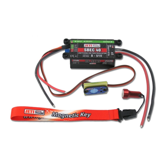
MAX BEC / SBEC 2.4.3 Switch - Magnetic switch The magnetic switch is designed to turn the MAX BEC 2D Plus on or off and is connected to it by a three-wire cable with a connector. To switch on the MAX BEC 2D Plus, it is necessary to place the supplied magnet in the carrier on the target so that the key of the carrier and the key on the magnetic switch are the same orientation. -
Page 12: Switch - Rc Switch
MAX BEC / SBEC MAX BEC / SBEC 2.4.4 Switch - RC switch MAX BEC 2D PLUS supports on/off via RC Switch. It can be easily used in JETI DC/DS transmitters. 1. Disconnect the connector with a lock on the three-wire cable and separate the magnetic switch. - Page 13 MAX BEC / SBEC MAX BEC / SBEC output voltage output voltage selection selection ACCU B ACCU A 13 EN...
-
Page 14: Switching Regulators
MAX BEC / SBEC MAX BEC / SBEC Switching regulators 3.1 SBEC 3.1 SBEC 3.1.1 Output voltage setting The output voltage is adjusted with the aid of a shorting plug (jumper) in steps of 5.0V, 5.5V, 6.0V, 7.0V and 8.0V. An important condition of keeping a correct output voltage in connection with the jumper position is a sufficiently high supply voltage. -
Page 15: Parameters Sbec
MAX BEC / SBEC MAX BEC / SBEC amount of applied load. When the heat protection is activated the output voltage decreases to several hundreds of mV. Notice: In order to ensure a proper function of the regulator always take care of an sufficient amount of cooling air throughflow. -
Page 16: Sbec 30D
MAX BEC / SBEC MAX BEC / SBEC 3.2 SBEC 30D 3.2 SBEC 30D 3.2.1 Output voltage setting Setup of the output voltage between 5 and 8.4V is accomplished in the JETI transmitter via EX BUS or in the JETIBOX (see chapter "Settings"). -
Page 17: Switch - Rc Switch
MAX BEC / SBEC MAX BEC / SBEC Target Led ON FIG. 7: Description of the magnetic switch and key Safety Precautions for the Manipulation of Magnets: Since the MAXBEC 2D Plus contains magnetic components, it is necessary to follow some simple rules for the handling of magnets. -
Page 18: Heat Protection
MAX BEC / SBEC MAX BEC / SBEC magnetic or RC switch to activate the unit. To switch-off, always use the magnetic or RC switch to turn-off the unit before disconnecting the batteries. 2. In order to ensure a proper function of the regulator always take care of an sufficient amount of cooling air throughflow. - Page 19 MAX BEC / SBEC MAX BEC / SBEC voltage (e.g. battery voltage) and the value of output voltage. Using buttons U and D (down and up arrows) of the JETIBOX it is possible to browse through the menu (direction to the main screen).
-
Page 20: Alternative Functions Logical Input
MAX BEC / SBEC MAX BEC / SBEC To switch between items, press left or right arrow for a longer period. Capacity Alarm – setting the level of capacity taken from the battery at which the alarm will sound Current Alarm – setting the level of current drawn from the battery at which the alarm wil sound MinVoltage Alarm –... -
Page 21: Configuration Via The Dc/Ds Transmitter
MAX BEC / SBEC MAX BEC / SBEC Never connect to a different voltage. The pin works exclusively on the Pull-Up mode.Pull-Up. 3.2.6.2 Configuration via the DC/DS transmitter The SBEC 30D can be configured by a DC/DS transmitter via the „Device Explorer“... - Page 22 MAX BEC / SBEC MAX BEC / SBEC Telemetry • BATT Voltage – actual battery voltage, input voltage • BATT Current – actual current drawn from the battery • BEC Voltage – actual output voltage of the BEC • BATT Capacity – actual capacity taken from the battery •...
- Page 23 MAX BEC / SBEC MAX BEC / SBEC • Max. BATT Voltage – the data of maximum input voltage, e.g. battery voltage • Max. BATT Current – the data of maximum current from the battery • Min. Temperature – the data of minimum temperature of the SBEC30D •...
-
Page 24: Parameters Sbec 30D
MAX BEC / SBEC MAX BEC / SBEC 3.2.7 Parameters SBEC 30D: Dimensions : 72x28x14 mm Weight : 50 g Recommended input voltage : 6 - 42 V Input voltage max. : 59 V Output voltage: 5.0 V- 8.4 V Sustained current : 8.2 A (with supply 2S LiXX) see tab. -
Page 25: Warranty
MAX BEC / SBEC MAX BEC / SBEC Warranty For the product we grant a warranty of 24 months from the day of purchase under the assumption that it has been operated in conformity with these instructions at recommended voltages and that it has not been damaged mechanically. - Page 26 Declares, that the product Type designation: Linear regulator Model number: Single BEC, MAX BEC, MAX BEC2, MAX BEC 2Dplus Country of origin: Czech republic The stated product complies with essential requirements of EMC 2014/30/EU, RoHS Directive 2011/65/EU and (EU) 2015/863.
- Page 27 MAX BEC / SBEC MAX BEC / SBEC ® Declaration of Conformity in accordance with the regulations of EU Directive EMC 2014/30/EU, RoHS 2011/65/EU and (EU) 2015/863 This declaration of conformity is issued under the sole responsibility of the manufacturer.
- Page 28 MAX BEC / SBEC MAX BEC / SBEC JETI model s.r.o. Lomená 1530, 742 58 Příbor Czech Republic www.jetimodel.com www.jetimodel.cz info@jetimodel.cz 28 EN...
Need help?
Do you have a question about the MAX BEC and is the answer not in the manual?
Questions and answers