Granberg Centerlift 960 Installation Instructions Manual
Hide thumbs
Also See for Centerlift 960:
- Installation instructions manual (24 pages) ,
- Operating & care instructions (2 pages)

Related Manuals for Granberg Centerlift 960


Summary of Contents for Granberg Centerlift 960
- Page 1 Dok. Nr: M960-ETL V: 1.0 2022-03-29 Installation Instructions Instructions d’installation Centerlift 960 WWW: Centerlift 960...
- Page 2 IMPORTANT SAFETY INSTRUCTIONS / PRESCRIPTIONS DE SÉCURITÉ IMPORTANTES EN When using an electrical furnishing, basic precautions should always be followed, including the following: Read all instructions before using the BASELIFT. DANGER - To reduce the risk of electric shock: 1. Always unplug this furnishing from the electrical outlet before cleaning. WARNING - To reduce the risk of burns, fire, electric shock, or injury to persons: 1.
- Page 3 Technical data / Données techniques EN Thank you for choosing to install a product from Granberg! In order for the product to work safely and securely, it is extremely essential that the installation instructions be followed. The installer should read and understand all the installation instructions before installation begins.
- Page 4 Planning / Planification EN Very Important! Check floor stability before installation. Maximum load on lifting unit is 440 lb (200kg) and dead load up to 220 lb (100kg). Ensure that the floor can withstand the concentrated load that occurs under motor units. Make sure that the motor units can be fixed to the floor and that the structure is not porous.
- Page 5 Alternative placement of electrical connection (inside engine unit) Au centre, sous le mélangeur Placement alternatif de la connexion électrique (à l'intérieur de l’unitémotrice) Hose Protection 61508-06 (Optional) Protection de tuyau 61508-06 (facultatif ) DWG NO. Granberg Interior AB Tel. +46(0)11197750 info@granberg.se TITLE: www.granberg.se DRAWN...
- Page 6 8x M8x20mm 8x BR M8 Cut aluminium profile for correct length Accessories / Accessoires ä t T I T : 1 : DWG NO. REVISION 08796 Granberg Interior AB Tel. +46(0)11197750 info@granberg.se TITLE: 61508-06 www.granberg.se DRAWN MATERIAL: FINISH: CHECKED WEIGHT:...
- Page 7 8x M8 CL960...
- Page 8 16x M8 CL960...
- Page 9 4x / consol - M8 CL960...
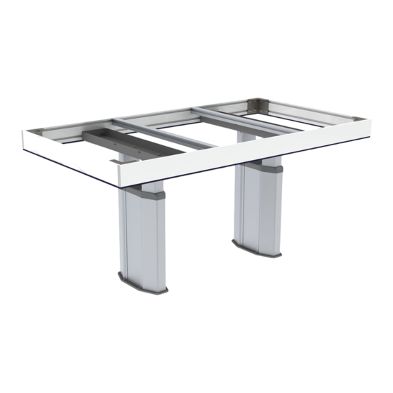
- Page 10 CL960...
- Page 11 EN Place the motor units with the right C-C distance according to the fixtures on the frame. The motor unit C-C distance is variable and may need to be adjusted to avoid colliding with the sinks. The fastenings on the frame can be moved by loosing 4x M8 bolts, sliding sideways, tightening bolts. FR Placez les unités motrices avec la bonne distance C-C en fonction des appareils sur le cadre.
- Page 12 16 mm 8x BR M8 8x M8 x 20mm CL960...
- Page 13 CL960...
- Page 14 Connect all cables as below Connectez tous les câbles comme ci-dessous Motor left 1 Moteur gauche 1 Motor left 2 Moteur gauche 2 Motor right 1 Moteur droit 1 Motor right 2 Moteur droit 2 Safety Stop Arrêt de sécurité Up / Down left Up / Down right Haut / Bas à...
- Page 15 WARNING – Ensure both power supply cords are connected before use AVERTISSEMENT – Avant utilisation, assurez-vous que les deux cordons d'alimentation sont branchés Now raise the lift unit to max by holding in the up button. Maintenant, soulevez l'unité de levage au maximum en maintenant le bouton vers le haut. CL960...
- Page 16 Make sure the motor units are parallel. Now screw the motor units to the floor. Use fasteners designed for the floor structure in question. 4x screws/motor unit. Assurez-vous que les unités motrices sont parallèles. Maintenant, vissez les unités motrices au sol. Utilisez des fixations conçues pour la structure du sol en question.
- Page 17 Side supports may need to be moved sideways so as not to collide with equipment integrated in the worktop. Loosen screws, adjust, tighten. Les supports latéraux peuvent devoir être déplacés latéralement, afin de ne pas entrer en collision avec l'équipement intégré...
- Page 18 Put on the worktop and screw into the corners of the frame. The worktop can also be glued to the top of the frame. Placez sur le plan de travail et vissez dans les coins du cadre. Le plan de travail peut également être collé sur le dessus du cadre. CL960...
- Page 19 Install the hose protection 61508-06 (Optional) Installer la protection du tuyau 61508-06 (facultatif ) Cut aluminium profile for correct length Centerlift 960 Fix in the floor DWG NO. REVISION 08796 Granberg Interior AB Tel. +46(0)11197750 info@granberg.se TITLE: 61508-06 www.granberg.se DRAWN...
-
Page 20: Functional Tests
Functional tests Complete functional tests should be carried out after installation: Ensure both power supply cords are connected before use! Test run the lift unit up and down all the way to each end position. Make sure that the lift runs freely without obstacles, risk of pinching and noise. - Page 21 Before you use the device - Read the users manual Only authorized persons may use the this product! Authorization means obligation to read and follow the instructions. It is very important that you read and understands the users manual before you use the device. The user manual is attached as a separate booklet.
- Page 24 Granberg Interior AB Box 6112 600 06, Norrköping Tel: 011-19 77 50 E-mail: info@granberg.se Internet: www.granberg.se...
Need help?
Do you have a question about the Centerlift 960 and is the answer not in the manual?
Questions and answers