Table of Contents
Advertisement
Available languages
Available languages
Quick Links
3
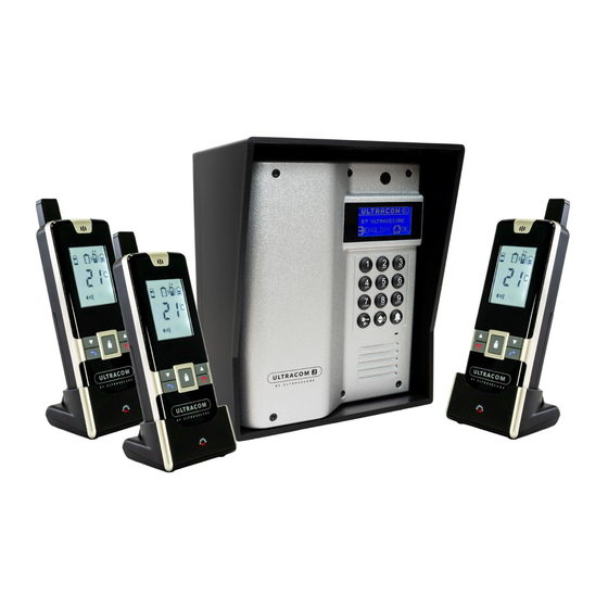
600 METRE WIRELESS INTERCOM (BATTERY or DC)
UP TO 9 REGISTERED RESIDENTS - REMOTE GATE/LATCH OPENING VIA
DIGITAL HANDSET OR KEYPAD - LCD SCREEN - BATTERY LIFE 18 MONTHS
- OPTIONAL 12-24VDC POWER SUPPLY - MOBILE HANDSET(S) ON BATTERY
INTERPHONE SANS-FIL 600 MÈTRES (PILES ou DC)
JUSQU'À 9 LOGEMENTS ENREGISTRÉS - OUVERTURE PORTAIL/GÂCHE À
DISTANCE ET VIA DIGICODE - ÉCRAN LCD - AUTONOMIE SUR PILES 18 MOIS -
ALIMENTATION 12-24VDC OPTIONNELLE - COMBINÉ(S) MOBILE(S) SUR BATTERIE
Advertisement
Chapters
Table of Contents

Related Manuals for UltraSecure ULTRACOM 3


Summary of Contents for UltraSecure ULTRACOM 3
- Page 1 600 METRE WIRELESS INTERCOM (BATTERY or DC) UP TO 9 REGISTERED RESIDENTS - REMOTE GATE/LATCH OPENING VIA DIGITAL HANDSET OR KEYPAD - LCD SCREEN - BATTERY LIFE 18 MONTHS - OPTIONAL 12-24VDC POWER SUPPLY - MOBILE HANDSET(S) ON BATTERY INTERPHONE SANS-FIL 600 MÈTRES (PILES ou DC) JUSQU’À...
- Page 2 Thank you for choosing Ultra Secure to monitor your property. The UltraCOM3 wireless intercom allows you to communicate with your visitors and open your gate or lock remotely (using the handset) or from the caller station using an unlocking pin. Up to 9 residents can be registered to the UltraCOM3 with an unlimited number of handsets per resident.
-
Page 3: Table Of Contents
Contents of your user guide Presentation of your UltraCOM3 wireless intercom ........ Presentation of the caller station ............Presentation of the mobile handset ............Presentation of the LCD screen of the handset .......... Meaning of the icons ................. Connection terminals ................. -
Page 4: Presentation Of Your Ultracom3 Wireless Intercom
Presentation of your UltraCOM3 wireless intercom Presentation of the caller station LCD screen (1) This LCD screen displays menu information and provides access to the various registered residents and opening by pin. Motion detector (PROX) (2) The motion detector turns on the caller station screen when a person is detected (see page 13). -
Page 5: Presentation Of The Mobile Handset
Protective cap (9) The protective cap protects the entrance to the aerial connection if it is not used. Battery slots (10) The UltraCOM3 board can operate using 4 type C batteries (not supplied) to be inserted in the slots provided, respecting the polarity. Presentation of the mobile handset “Pick up”... -
Page 6: Presentation Of The Lcd Screen Of The Handset
Volume key - (17) This button is used to decrease the ring and communication volume (see page 18). In combination with the volume +, it is used to choose the alert mode (see page 18). Handset battery access button (18) This button opens the handset battery cover. -
Page 7: Meaning Of The Icons
Meaning of the icons Caller station indicator Ring alert only Missed call notification Alert by visual indicator only Communication indicator Vibration alert only Remote opening disabled Alert by ring and visual indicator Remote opening trigger indicator Ring and vibration alert Alert by vibration and visual Handset battery at critical level indicator... -
Page 8: Ultracom3 Intercom Power Supply
UltraCOM3 intercom power supply Door station power supply The caller station can be operated on batteries. The observed battery life is 12 to 18 months. You can also choose to power it directly 12-24V from several sources (transformer, gate power supply, solar panel, …) as long as it is a direct current (DC) and 12 or 24V. -
Page 9: Handset Low Battery Information
• The charging indicator should light up red during the charging process. Adjust the position of the handset in the charger if this light does not come on. During charging, the icon flashes until your handset is fully charged. • The handset fully charges in approximately 4 hours on first use. -
Page 10: Ultracom3 Commissioning
UltraCOM3 commissioning When starting up the UltraCOM3 for the first time, the caller station will ask you to choose the language BY ULTRASECURE BY ULTRASECURE of the menu (French or English). To choose, scroll using the button and then confirm by pressing... -
Page 11: Ultracom3 Settings
UltraCOM3 settings In order to access the various menu settings, you will need to unlock the caller station. To do this, if you are using the UltraCOM3 for the first time, follow the UltraCOM3 commissioning procedure, described on previous page. If your caller station already in place, follow the unlocking procedure below. -
Page 12: External Volume
When all the handsets are in pairing mode, confirm PAIRING ‘1’: PAIRING ‘1’: the pairing on the caller station by pressing the PAIRING OK PAIRING OK button . A confirmation beep and the message PAIRING RESIDENTS RESIDENTS OK will confirm the pairing. You can then return to the Residents menu by pressing the button . -
Page 13: Outdoor Tone
Outdoor tone The outdoor tone sounds when a visitor rings the intercom. You have the option of activating the outdoor tone or not. To do this, unlock the caller station (see page 11), scroll through the menus using the button and enter the OUTDOOR TONE menu using the button . -
Page 14: Aerial
To select the switching on mode of your choice, unlock the caller station (see page 11), scroll through the menus using the button and enter the SCREEN ON menu. SCREEN using the button . Then choose the desired switching on mode using the button . -
Page 15: Frequency
By default, the aerial mode is set to INTERNAL. Frequency The FREQUENCY menu is reserved for our technical teams. Change the frequency of the UltraCOM3 caller station only if specifically requested. Unlock Pin The unlock pin is used to activate the caller station UNLOCK PIN: UNLOCK PIN: relay in order to open the wired element (gate, latch... -
Page 16: Language
Language The UltraCOM3 caller station has a menu available LANGUAGE LANGUAGE in French and English. To choose the UltraCOM3 FRENCH FRENCH language, unlock the caller station (see page 11), scroll through the menus using the button EXIT EXIT enter the LANGUAGE menu using the button Select FRENCH or ENGLISH using the button and confirm by pressing the button Information... - Page 17 Important: if you forget the menu pin, you can reset the UltraCOM3 manually at the back of the caller station. To do this, open the caller station (see page 22) and connect the two manual reset terminals (see page 4) to each other using a paperclip or copper wire.
-
Page 18: Settings Of Ultracom3 Handsets
Settings of UltraCOM3 handsets Switch the handset on/off To switch the handset on or off, you can simply press and hold the ON/OFF key . Also note that a switched off handset will automatically switch on when placed on its charging station. Warning: a switched off handset cannot receive calls from the caller station. -
Page 19: Using The Ultracom3 Intercom
Using the UltraCOM3 intercom Make sure that the caller station is powered (12-24VDC power supply or alkaline batteries, see page 8). When all your settings and pairings are done, you can then use your intercom. Opening using the pin You can open your gate/latch (if an element is wired on the caller station) by using the button . -
Page 20: Gate/Latch Remote Opening
• Conversation is now possible and the visitor’s voice can be heard in the handset loudspeaker. To answer the visitor, press and hold the push-to-talk button (PTT) and speak into the microphone. Release the push-to-talk button when you have finished talking to receive communication from the caller station. Please note that the visitor’s voice is muted while pressing the push-to-talk button. -
Page 21: Reverse Call Function (From Handset To Caller Station)
• Disable the remote opening function: With the handset turned on, briefly press the button , then within 2 seconds, press the button quickly. The remote opening function disabling icon appears on the instrument panel screen. • Enable the remote opening function: Perform the same manipulation as above, the icon disappears and the function is active again. -
Page 22: Installation Of The Caller Station
Installation of the door station Opening the caller station Unscrew the 6 screws on the front of the roadside caller station using the tool provided to open the unit. The screws are secure, it is necessary to keep the tool provided in a safe place as you will need it later for the maintenance of your caller station. -
Page 23: Connection For Gate/Latch (N/O - N/C - Com)
• Open the caller station using the tool provided and pass the wires through the base via the cable gland. Be careful not to lose the 6 small specific screws for opening the caller station! • Screw the caller station base to the hood (using the 8 screws provided). -
Page 24: Auxiliary Output (Aux)
In DC power supply, if you need a transient 12-24V output (for triggering a lock for example), you can loop (shunter) the + via your Com relay (see diagram below). On batteries, only a momentary normally closed or open dry contact (0v) is available. ULTRACOM Loop Latch... -
Page 25: Tips For Using The Keypad
Tips for using the Keypad The Keypad is made up of keys with several letters. To choose a letter, it will be necessary to press the same number of times as its position on the key. For example, to dial the letter C, you will have to press the 2 key three times. -
Page 26: Precautions For Use
Precautions for use • Only use the supplied charger to charge your handset. Using another non- compliant charger could damage your handset. • Never mix new and used batteries. • If you do not intend to use your UltraCOM3 intercom for an extended period, we recommend that you remove all the batteries from the elements and store your equipment under cover. -
Page 27: Technical Specifications
Technical specifications Caller station Power supply possible 4 x C batteries (not included) or 12-24V DC Backup battery Yes, via batteries (if connected in 12-24V DC) Wireless range 600 meters (open field) Dimensions 150mm (H) x 125mm (L) x 40mm (D) Screen size 4cm diagonal Aerial... - Page 28 Environmental Information for Customers in the UK & EU If the product no longer works or can no longer be repaired, it must be disposed of in accordance with applicable regulations. Disposal of used batteries and accumulators: You are legally obliged to return used batteries and accumulators (under the Battery and Accumulator Ordinance).
- Page 29 Notre guide vous permettra de découvrir et d’installer ce matériel, mais aussi d’optimiser vos réglages, pour un équipement parfaitement adapté à votre environnement. Bonne découverte et prise en main de votre interphone sans-fil UltraCOM3. L’équipe Ultra Secure France. contact@securitemarche.fr 09 72 30 88 88 ULTRA SECURE ultrasecure.fr...
- Page 30 Ouverture de la platine ..............Fixation de votre platine de rue ............Raccord pour portail/gâche (N/O - N/C - Com) ........Sortie auxiliaire (AUX) ............... Conseils d’utilisation du clavier ............Précautions d’emploi ..............Guide de dépannage ..............Spécifications techniques ............... ULTRA SECURE ultrasecure.fr...
-
Page 31: Présentation De Votre Interphone Sans-Fil Ultracom3
En cas d’oubli du code menu, vous avez la possibilité de réinitialiser l’UltraCOM3 manuellement (voir page 44). Raccord d’antenne déportée optionnelle (8) Ce câble permet de raccorder une antenne déportée (non fournie) si une meilleure portée de transmission est nécessaire. ULTRA SECURE ultrasecure.fr... -
Page 32: Présentation Du Combiné Mobile
Microphone (15) Il permet de communiquer avec la platine et avec les autres combinés. Touche volume + (16) Ce bouton permet d’augmenter le volume de la sonnerie et de la communication ULTRA SECURE ultrasecure.fr... -
Page 33: Présentation De L'écran Lcd Du Combiné
Témoin de déclenchement Type d’alerte relais à distance Indicateur d’appel Niveau de batterie du combiné Témoin de piles faibles de la platine Température intérieure Désactivation ouverture à distance Témoin de communication Niveau de volume Notification d’appel manqué ULTRA SECURE ultrasecure.fr... -
Page 34: Signification Des Icônes
Bornier du câble d’alimentation DC - DC + Bornier du câble d’alimentation DC + Bornier commun aux deux sorties relais Bornier de sortie relais “Normalement fermé” Bornier de sortie relais “Normalement ouvert” Bornier pour sortie auxiliaire Bornier pour sortie auxiliaire ULTRA SECURE ultrasecure.fr... -
Page 35: Alimentation De L'interphone Ultracom3
être branché. Pour cela suivez la procédure suivante : • Connectez la fiche d’alimentation à l’arrière du socle puis branchez le transformateur à une prise murale. • Placez le combiné sur son socle de recharge. Si le combiné est éteint, il s’allumera ULTRA SECURE ultrasecure.fr... -
Page 36: Information De Batterie Faible Du Combiné
Déconnectez ensuite la batterie de la fiche. Important : si remplacement de la batterie du combiné, veuillez vous assurer que la référence soit adaptée, sans quoi il existe un risque d’explosion. Vous pouvez retrouver les références adaptées sur notre site. ULTRA SECURE ultrasecure.fr... -
Page 37: Mise En Service De L'ultracom3
Mise en service de l’UltraCOM3 Lors de la première mise en route de l’UltraCOM3, la platine demandera de choisir la langue du menu BY ULTRASECURE BY ULTRASECURE (français ou anglais). Pour choisir, faites défiler à l’aide du bouton puis validez en appuyant sur le... -
Page 38: Paramétrages De L'ultracom3
JUMELAGE ‘1’: Jumelage (Pairing) du(des) combiné(s) à jumeler avec ce logement. Pour cela, éteignez le(les) ACTIVER ‘P’ ACTIVER ‘P’ combiné(s) concerné(s) en maintenant la touche RETOUR RETOUR et rallumez-le(les) en maintenant simultanément les touches . Le clignotant indique ULTRA SECURE ultrasecure.fr... -
Page 39: Volume Extérieur
Pour cela, déverrouillez la platine (voir page 38), faites défiler les menus à l’aide du bouton et entrez dans le menu VOLUME EXT. à l’aide du bouton . Choisissez ensuite le niveau de volume désiré de 1 à 5 à l’aide du ULTRA SECURE ultrasecure.fr... -
Page 40: Carillon Extérieur
• Détection de mouvement forte (DETECTION +) : l’écran s’allume quand il détecte un mouvement à une distance d’environ 5 mètres. • Détection de mouvement faible (DETECTION -) : l’écran s’allume quand il ULTRA SECURE ultrasecure.fr... -
Page 41: Antenne
Important : si vous n’avez pas d’antenne déportée, le mode d’antenne doit être réglé sur INTERNE. Le système utilisera alors l’antenne interne. Le câble souple de connexion n’est alors pas utilisé et peut être laissé simplement au dos de la platine (avec son capuchon rouge). ULTRA SECURE ultrasecure.fr... -
Page 42: Fréquence
à 8 chiffres à l’aide du clavier. Appuyez ensuite sur le bouton afin de valider votre code. Retenez bien votre code menu, celui-ci est indispensable pour déverrouiller la platine. En cas d’oubli de ce code, une réinitialisation complète sera nécessaire (voir page 44). ULTRA SECURE ultrasecure.fr... -
Page 43: Langue
CONFIRMER ? bouton . La platine vous demande de confirmer votre action. Vous pouvez alors valider à l’aide du bouton ou annuler à l’aide du bouton . Si vous validez, la platine va alors réinitialiser et redémarrer. ULTRA SECURE ultrasecure.fr... - Page 44 à l’arrière de la platine. Pour cela, ouvrez la platine (voir page 49) et connectez entre elles les deux bornes de réinitialisation manuelle (voir page 31) à l’aide d’un trombone ou d’un fil de cuivre. ULTRA SECURE ultrasecure.fr...
-
Page 45: Paramétrages Des Combinés Ultracom3
Pendant la conversation, vous pouvez régler le volume du haut-parleur à l’aide des touches . L’icône de volume évolue en fonction du réglage. Le volume de la sonnerie du combiné peut également être ajusté en utilisant les mêmes touches hors communication. Le symbole vous indiquera visuellement votre sélection. ULTRA SECURE ultrasecure.fr... -
Page 46: Utilisation De L'interphone Ultracom3
Pour répondre au visiteur, maintenez enfoncé le bouton de conversation (PTT) et parlez dans le microphone. Relâchez le bouton de conversation lorsque vous avez fini de parler afin de recevoir la ULTRA SECURE ultrasecure.fr... -
Page 47: Ouverture À Distance Portail/Gâche
à n’importe quel moment. Pour éviter les fausses manipulations (par les enfants par exemple), cette fonction d’ouverture à distance peut être désactivée. Quand désactivée, l’appui sur la touche n’aura aucun effet. ULTRA SECURE ultrasecure.fr... -
Page 48: Fonction Appel Inversé (Combiné Vers Platine)
Le choix du combiné vers lequel est émis l’appel n’est pas possible. Quand un combiné commence un appel, tous les autres combinés (jumelés sur le même logement) sonnent et peuvent répondre. Cependant, seul le premier combiné qui décroche pourra converser, tous les autres seront exclus. ULTRA SECURE ultrasecure.fr... -
Page 49: Installation De La Platine De Rue
(alimentation, connexion portail, antenne déportée, …) par le mur et l’orifice central de la visière prévu à cet effet. • Installez votre visière au mur en utilisant les vis fournies (ou adaptées à la surface d’installation). ULTRA SECURE ultrasecure.fr... -
Page 50: Raccord Pour Portail/Gâche (N/O - N/C - Com)
40) le relais lors d’un appui sur le bouton de déverrouillage combiné ou d’une ouverture par code. Note : cette borne NC permet de câbler une gâche à rupture. • Normalement ouvert (N/O) Veuillez connecter votre élément (portail, gâche...) aux bornes N/O et Com du ULTRA SECURE ultrasecure.fr... - Page 51 éteindre votre platine, vérifier vos connexions au bornier et relancer l’appareil. Si vous avez bouclé votre alimentation DC 12-24V et si la gâche de porte électrique ne fonctionne pas, veuillez inverser la polarité de votre relais/ gâche et réessayez. ULTRA SECURE ultrasecure.fr...
-
Page 52: Sortie Auxiliaire (Aux)
Un appui long sur les touches n’aura aucun effet. Exemple pour la touche 2 Exemple pour la touche 3 1 appui 1 appui 2 appuis 2 appuis 3 appuis 3 appuis 4 appuis 4 appuis 5 appuis 5 appuis ULTRA SECURE ultrasecure.fr... -
Page 53: Précautions D'emploi
Mis à part ce qui est décrit dans ce document, ne démontez pas davantage les éléments, aucune pièce ne peut être réparée ou remplacée. • Avant d’utiliser un combiné pour la première fois, veuillez le recharger complètement pendant 4 heures. ULTRA SECURE ultrasecure.fr... -
Page 54: Guide De Dépannage
Les batteries sont faibles Rechargez les combinés sur leur socle Le témoin de niveau de La batterie du combiné Remplacez la batterie du combiné batterie du combiné est est endommagée et ne (disponible sur notre site) allumé en permanence peut plus être rechargée ULTRA SECURE ultrasecure.fr... -
Page 55: Spécifications Techniques
40mm (H) x 62mm (L) x 50mm (P) Option combiné à combiné Entrée chargeur 100 - 240V AC Sortie chargeur 5V DC 1A Fréquence d’opération 863 - 869 Mhz Portée sans-fil 600 mètres (champ libre) Affichage de la température Température intérieure ULTRA SECURE ultrasecure.fr... - Page 56 Informations environnementales pour les clients de l’Union Européenne Si le produit ne fonctionne plus ou ne peut plus être réparé, il doit être éliminé conformément aux réglementations en vigueur. Élimination des piles et des accumulateurs usagés : Vous êtes légalement tenu de rapporter les piles et les accumulateurs usagés (en vertu du décret relatifs aux piles et aux accumulateurs).
Need help?
Do you have a question about the ULTRACOM 3 and is the answer not in the manual?
Questions and answers
With the Ultra3com 4 phone system, where do the wires for the door release get connected to the unit and how do I identify which of the wires from the door release is the n/c and which is the n/o?
To connect the door release wires to the UltraSecure ULTRACOM 3 system:
1. Identify the relay terminals on the terminal block of the caller station: Normally Closed (N/C), Normally Open (N/O), and Common (Com).
2. For a breakaway latch, connect it to the N/C and Com terminals. When the unlock button is pressed or a valid PIN is entered, the relay will temporarily open.
3. For a release latch, connect it to the N/O and Com terminals. When the unlock button is pressed or a valid code is entered, the relay will temporarily close.
4. If using a DC power supply and needing a 12–24V output for triggering a lock, you can loop the + voltage through the Com relay.
5. On battery power, only a momentary dry contact (0V) is available through N/C or N/O.
Identify N/C and N/O wires based on their terminal labels on the terminal block:
- N/C = Normally Closed
- N/O = Normally Open
- Com = Common
This answer is automatically generated